122
~
3. CIRCUIT DESCRIPTION
The
following
conditions
are
assumed:
* The deck
is
initially
in the stop mode unless
otherwise specified.
* Voltages, waveforms, and operating times
given in the
text
are
typical ones
for
reference.
* I n the description
of
ampl ifiers (sections
3-11
through
3-14), generallly, the
left
channel
is
described.
* In the illustrations,
circuit
boards, terminals,
and connectors
are
omitted.
* Part numbers are assigned
as
follows:
100-199:
Muting
circuit,
bias osciUator cir·
cuit,
and L-channel record/repro-
duce
circuit
mounted on record/
reproduce &
control
PCB
200-299:
R-channel record/reproduce
cir·
cuit
on record/reproduce & con-
trol
PCB
300-399:
L-channel
monitor,
record, and
HX
circuits and common L- and
R-channel
circuits
mounted
on
lever switch
PCB
400-499:
R-channel
monitor,
record, and
HX
circuits
mounted
on lever
switch
PCB
500-599:
Power supply
PCB
circuits.
600-699:
System
control
circuits and
mechanical parts mounted on
reo
cord/reproduce &
control
PCB
and
joint
PCB
700-799:
L-channel meter
circuit
and phone
amplifier
circuit
mounted
on
meter
amplifier
PCB
800-899:
R-channel meter
circuit
and phone
amplifier
circuit
mounted
on
meter
amplifier
PCB
CONTROL SECTION
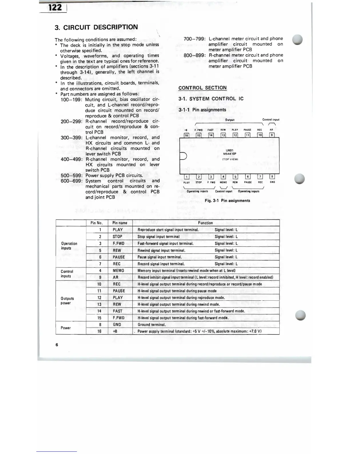
3-1. SYSTEM CONTROL
IC
3-1-1 Pin assignments
Output Control input
Ir
~
----------
----------~\
r-\
.8
F.
FWO
FAST
REW
PLAY
PAUSE
AR
US01
M54410P
(T
O P
VIEWI
PLAY
STOP
f . fWO
MEMO
REW
PAUSE
REt
GNO
\~
______
....JI
'--.I
,
'-
____
---11
OperOling
inpulS Control input Operating inpulS
Fig. 3-1 Pin assignments
Pin
No
.
Pin
name
Function
1
PLAY
Reproduce
start
signal
input terminal.
Signal
level:
L
2
STOP
Stop
signal
input
term
inal
Si
gnal
level
: L
Operation
3
F.
FWD
Fast-forward
signal
input terminal.
Signal
level
: L
inputs
5
REW
Rewind
signal
input terminal.
Signallavel: L
6
PAUSE
Pause
signal
input terminal.
Signal
level
: L
7
REC
Record
signal
input terminal.
Signal
level:
L
Control
4
MEMO
Memory
input terminal (resets
rewind
mode
when
at L
level)
inputs
9
AR
Record
inhibit
signal
input
terminal
(L
level:
record
inhibited, H
level:
record
enab
led)
10
REC
H-Ievel
signal
output terminal
during
record/reproduce
or
record/pause
mode
11
PAUSE
H
-level
signal
output terminal
during
pause
mode
Outputs
12
PLAY
H-Ievel
signal
output terminal
during
reproduce
mode.
power
13
REW
H-
Ievel
signal
output terminal
during
rewind
mode
.
14
FAST
H-Ievel
signal
output terminal
during
rewind
or
fast-forward
mode.
15
F.FWD
H-Ievel
signal
output terminal
during
fast-forward
mode.
Power
8
GND
Ground
terminal.
16
+B
Power
supply
terminal (standard:
+5
V +/-10%, absolute
maximum:
+7.0
V)
I
6