-----
1
122
3-14.
DOLBY
HX
CIRCUIT
NOTE: The
Dolby
Headroom Extension system
(Dolby
HX
system)
is
provided in the
record
circuit
of
the deck and operates
only
in the
following
conditions.
NR SYSTEM switch: NR +
HX
SPEED switch:
STANDARD
BIAS switch: Co
(Cr02)
or
NORMAL
EQ switch: Co (Cr02 )
or
NORMAL
Mode: record/reproduce mode
3-14-1 Bias characteristics
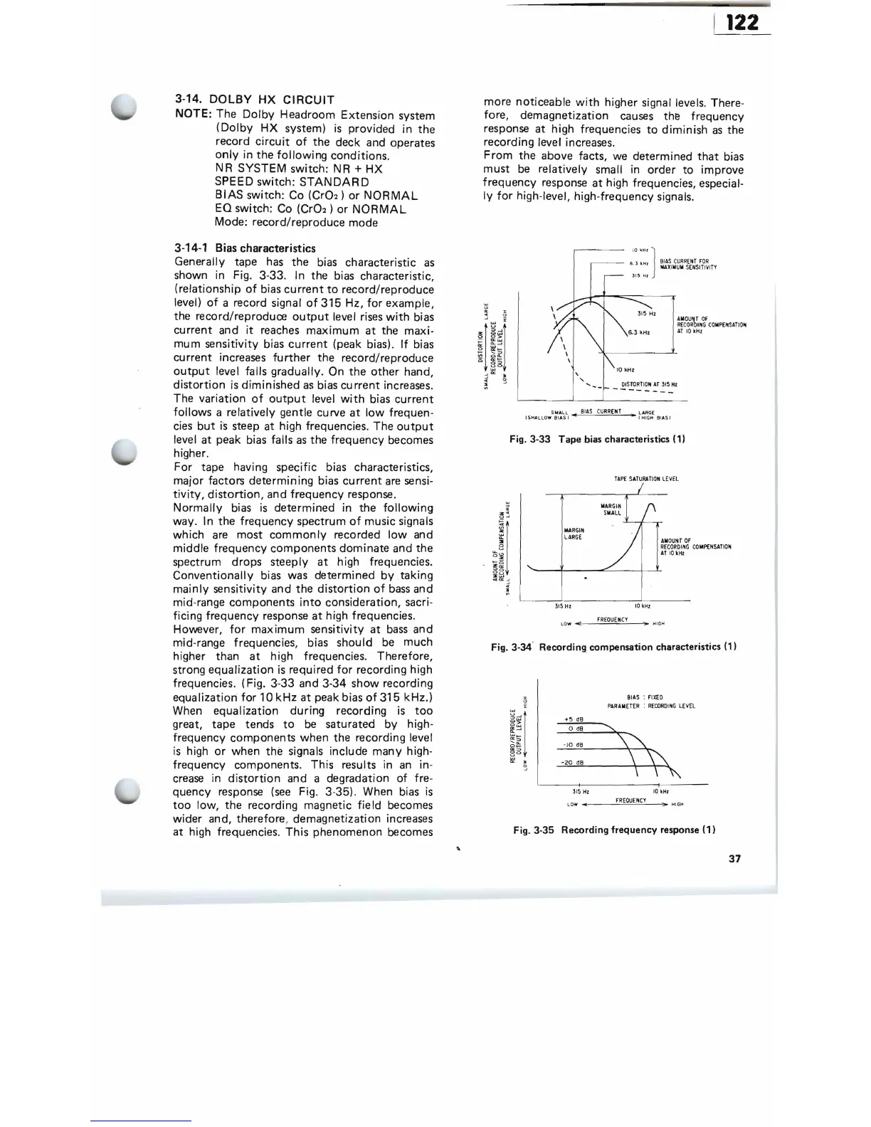
Generally tape
has
the
bias
characteristic
as
shown in Fig. 3-33. In the bias characteristic,
(relationship
of
bias
current
to
record/reproduce
level)
of
a record signal
of
315 Hz,
for
example,
the record/reproduce
output
level
rises
with
bias
current and
it
reaches
maximum
at
the maxi-
mum
sensitivity bias
current
(peak bias).
If
bias
current increases
further
the record/reproduce
output
level falls gradually. On the other hand,
distortion
is
diminished
as
bias
current
increases.
The variation
of
output
level
with
bias
current
follows a relatively gentle curve
at
low
frequen-
cies
but
is
steep at high frequencies. The
output
level at peak bias falls
as
the frequency becomes
higher.
For tape having specific bias characteristics,
major factors determining bias
current
are
sensi-
tivity,
distortion,
and frequency response.
Normally
bias
is
determined in the
following
way. In the frequency spectrum
of
music signals
which
are
most
commonly
recorded
low
and
middle frequency components dominate and the
spectrum drops steeply
at
high frequencies.
Conventionally bias was determined
by
taking
mainly
sensitivity and the
distortion
of
bass
and
mid-range components
into
consideration, sacri-
ficing frequency response
at
high frequencies.
However,
for
maximum
sensitivity
at
bass
and
mid-range frequencies, bias should
be
much
higher than
at
high frequencies. Therefore,
strong equalization
is
required
for
recording high
frequencies. (Fig. 3-33 and 3-34 show recording
equa
lization
for
10k
Hz
at
peak bias
of
315 kHz.)
When equalization
during
recording
is
too
great, tape tends
to
be
saturated by high-
frequency components when the recording level
is
high
or
when the signals include many high-
frequency components. This results in
an
in-
crease
in
distortion
and a degradation
of
fre-
quency response
(see
Fig. 3-35). When bias
is
too
low, the recording magnetic
field
becomes
wider and, therefore, demagnetization increases
at high frequencies. This phenomenon becomes
more noticeable
with
higher signal levels. There-
fore, demagnetization
causes
the frequency
response at high frequencies
to
diminish
as
the
recording level increases.
From
the above facts, we determined
that
bias
must
be
relatively small in order
to
improve
frequency response
at
high frequencies, especial-
ly
for
high-level, high-frequency signals.
~_
_
10
'"
' ] B
IAS
CU
RRfNT
FOR
I S. l
IIMr
MA
X
IMUM
S
ENSITIV
I
TY
3L5
HI
,
DISTO
RTI
ON
AT
ll5
Hz
"
SIroIAlL
BIAS
C
URRENT
L ARGE
(
SHA
LLO
W BI AS I
"til
... C H
IG
H BI A
S)
Fig.3-33
Tape
bias characteristics (1)
TA
PE
SAT
U
RA
TI
ON
LEVEL
MARGIN
LARG
E
AM
OU
NT
OF
R
ECORD
I
NG
C
OMI't:NSAT
I
ON
AT
10
kHz
ll5
Hz
10
kHl
LOW
....
_
.;..;FR=EO=UE=NC:..;.Y_~'>
HIGH
Fig. 3-34- Recording_
compensation
characteristics (1)
%
BIAS
:
FlX£D
~
i'
P
ARAMETER
:
RECORDING
LEVE
L
"'~
. 5
dB
0,.
o~
o dB
if--'
~-
"~I
"''''
,,-
'
0_
-
10
dB
3
"''''
0
II!
3
-2
0
dB
•
ll
5
Hz
10
kHI
FREO
U
EN
CY
LO
W
':> H I
GH
Fig. 3-35 Recording
frequency
response (1)
37