122
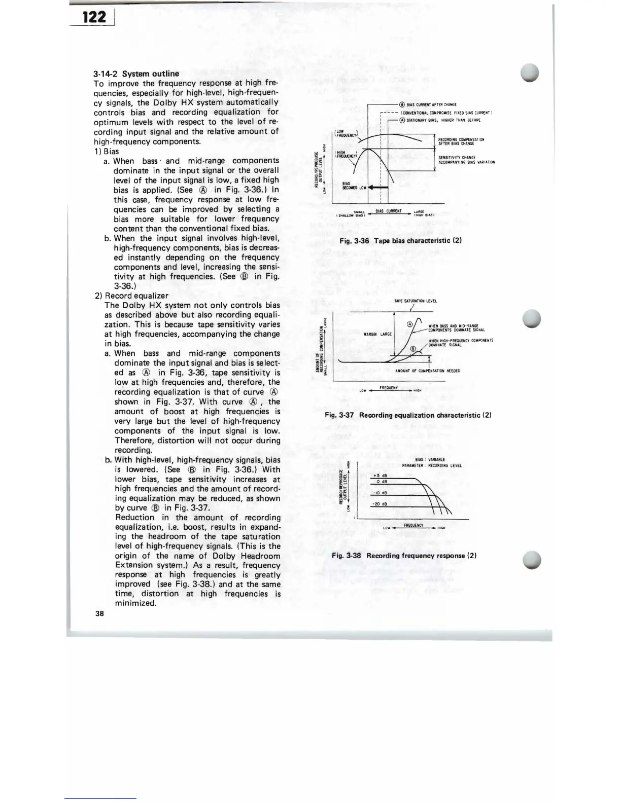
3-14-2 System
outline
To
improve
the
frequency
response
at
high fre-
quencies, especially
for
high-level, high-frequen-
cy
signals, the
Dolby
HX
system
automatically
controls
bias and recording
equalization
for
optimum
levels
with
respect
to
the
level
of
re-
cording
input
signal and the relative
amount
of
high-f
,requency components.
1) Bias
a.
When
bass
- and mid-range
components
dominate
in the
input
signal
or
the
overall
level
of
the
input
signal
is
low,
a
fixed
high
bias
is
applied.
(See
®
in
Fig. 3-36.) In
this
case,
frequency
response
at
low
fre-
quencies can
be
improved
by
selecting a
bias
more
suitable
for
lower
frequency
content
than the
conventional
fixed
bias.
b. When
the
input
signal involves high-level,
high-frequency
components, bias is decreas-
ed
instantly
depending
on
the
frequency
components and level, increasing the sensi-
tivity
at
high frequencies.
(See
@
in
Fig_
3-36.)
2) Record equalizer
The
Dolby
HX
system
not
only
controls
bias
as
described above
but
also recording equali-
zation.
This
is because tape
sensitivity
varies
at
high frequencies,
accompanying
the change
in bias.
a.
When
bass
and mid-range
components
dominate
the
input
signal and bias is select-
ed
as
®
in
Fig. 3-36, tape
sensitivity
is
low
at
high frequencies and,
therefore,
the
recording
equalization
is
that
of
curve ®
shown in Fig. 3-37.
With
curve
®,
the
amount
of
boost
at
high frequencies
is
very
large
but
the level
of
high-frequency
components
of
the
input
signal is low.
Therefore,
distortion
will
not
occur
during
recording.
b.
With
high-level, high-frequency signals, bias
is lowered.
(See
@
in
Fig. 3-36.)
With
lower
bias, tape
sens
i
tivity
increases
at
high frequencies and the
amount
of
record-
ing equalization may
be
reduced,
as
shown
by
curve @
in
Fig. 3-37.
Reduction
in
the
amount
of
recording
equalization, i.e. boost, results in expand-
ing the headroom
of
the
tape
saturation
level
of
high-frequency
signals.
(This
is
the
origin
of
the
name
of
Dolby
Headroom
Extension system.) As a resul,
t,
frequency
response
at
high frequencies
is
greatly
improved
(see
Fig.
3-38.)
and
at
the
same
time
,
distortion
at
high frequencies
is
minimized.
38
,---
® BI
AS
C
~NT
AFTER
C!<ANGE
i - - - - I
CONVENTIONAL
CO
MPR
O
MIS
E F
IX
ED
BIAS
CU
RRt:N
T J
: ®
STATIONARY
BIAS
,
HI
GH
ER
THAN
BE
FORE
RE
C
ORD
ING
COMPENSA
TIO
N
AF~ER
BIAS
C
HAN
GE
SENSITIV
IT
Y
CHAN
GE
AC
C
OMPANYING
BIA
S
vARIATI
ON
L
.~
£
,.
(
fi
I
GH
8
.ASJ
Fig.
3-36
Tape bias characteristic (2)
TAPE
SATURAT
IO
N
LEvEL
WHEN
BA
SS
AND
MID-
RANGE
COMPONENTS
DOMINA
TE
SI
G
NAL
MARGIN
LAR
GE
"HEN
HIGH-FREQUEN
CY
C
OM
PO
NENTS
DO
MINATE
S
IGNAL
AMOUNT
OF
C
OMPENSA
TI
ON
NHDED
LOW
_.
---,-,FR~EQc:::UE,,-,NY
__
• Hoe H
Fig. 3-37 Recording equalization characteristic (2)
BI
AS
:
VARIABLE
G
PARAMETER
:
RE
CO
RDING
LE
v
EL
lj
i
&~
+ 5
dB
o
dB
~~
II!'~
-10
dB
~~
§o
-20
dB
'"
~
FlIE
Q
UE
NC
Y
l OW • •
WIG
M
Fig. 3-38 Recording frequency response (2)
 Loading...