122
I
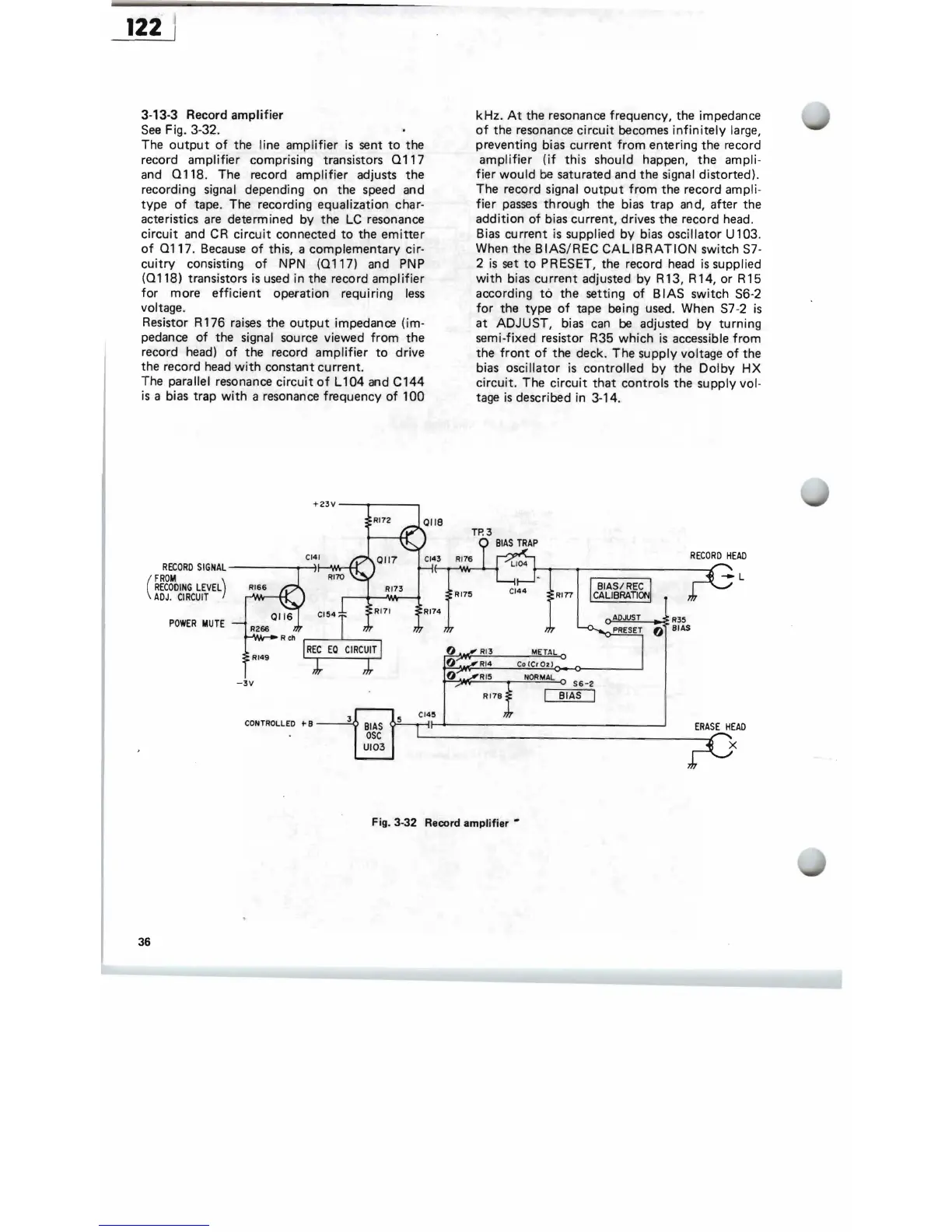
3-13-3 Record
amplifier
See
Fig. 3-32.
The
output
of
the line
amplifier
is
sent
to
the
record
amplifier
comprising transistors
0117
and
0118.
The record
amplifier
adjusts
the
recording signal. depending on the speed and
type
of
tape. The recording equalization char-
acteristics
are
determined by the
LC
resonance
circuit
and
CR
circuit
connected
to
the
emitter
of
0117.
Because
of
this, a complementary cir-
cuitry
consisting
of
NPN
(0117)
and PNP
(0118)
transistors
is
used in the record
amplifier
for
more
efficient
operation requiring
less
voltage.
Resistor R 176
raises
the
output
impedance (im-
pedance
of
the signal source viewed
from
the
record head)
of
the record
amplifier
to
drive
the record
head
with
constant current.
The parallel resonance
circuit
of
L 104 and C144
is
a bias trap
with
a resonance frequency
of
100
kHz.
At
the resonance frequency, the impedance
of
the resonance
circuit
becomes
infinitely
large,
preventing bias current
from
entering the record
amplifier
(if
this
should happen,
the
ampli-
fier
would
be saturated and the
Signal
distorted).
The record signal
output
from
the record ampli-
fier
passes
through the bias trap and, after the
addition
of
bias current, drives the record head.
Bias
current
is supplied
by
bias oscillator U 103.
When the B
IAS/REC
CALIBRATION
switch
S7-
2
is
set
to
PRESET, the record head
is
supplied
with
bias
current
adjusted by R13, R14,
or
R15
according
to
the setting
of
B
lAS
switch S6-2
for
the
type
of
tape being used. When
S7
-2
is
at
ADJUST,
bias
can
be
adjusted
by
turning
semi-fixed resistor R35
which
is
accessible
from
the
front
of
the deck. The supply voltage
of
the
bias oscillator
is
controlled
by
the
Dolby
HX
circuit.
The
circuit
that
controls
the
supp'ly vol-
tage
is
described in 3-14.
RECORD
SIGNAL
----""T'"..,~-At.,\__f'_[
(
FROM
)
RECODING
LEVEL
ADJ.
CIRCUIT
RI66
POWER
MUTE
R266
RI49
-3V
RECORD
HEAD
Rln
o=='---~
R35
o
BIAS
56-2
BIAS I
CONTROLLED
to
B
-----=-'f
:1.
r-c_~
______________
~
__
jD_E_R-I.ASE
H;AD
Fig.3-32
Record amplifier ..
36
 Loading...