[
122
R713
R714
r
0703
+~.3V----------~---------------------------------------,
FROM
METER
AMPL.
C708
R716
PEAK
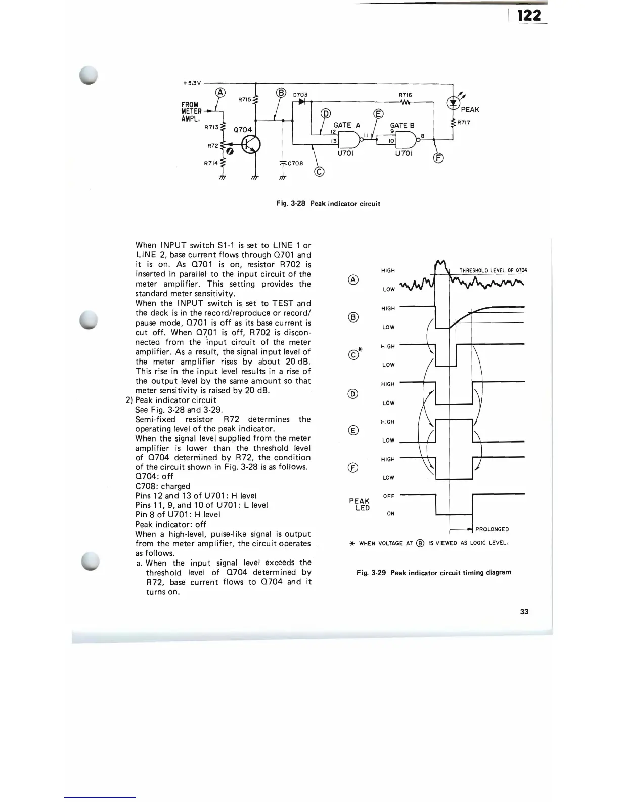
Fig. 3-28 Peak
indicator
circuit
When INPUT switch
S1-1
is
set
to
LINE
1
or
LINE
2,
base
current
flows through
0701
and
it
is
on.
As
0701
is
on, resistor R702
is
inserted in parallel
to
the
input
circuit
of
the
meter
amplifier.
This setting provides
the
standard meter sensitivity.
When
the
INPUT switch
is
set
to
TEST and
the deck
is
in
the
record/reproduce
or
record/
pause
mode,
0701
is
off
as
its
base
current
is
cut
off.
When
0~01
is
off,
R702
is
discon-
nected
from
the
input
circuit
of
the meter
amplifier. As a result, the signal
input
level
of
the meter
amplifier
rises
by
about
20 dB.
This rise in
the
input
level results in a
rise
of
the
output
level
by
the
same
amount
so
that
meter sensitivity
is
raised
by
20 dB.
2)
Peak
indicator
circuit
See
Fig. 3-28 and 3-29.
Semi-fixed resistor R72 determines the
operating level
of
the peak indicator.
When the signal level supplied
from
the meter
amplifier
is
lower than the threshold level
of
0704
determined
by
R72, the
condition
of
the
circuit
shown in Fig. 3-28
is
as
follows.
0704:
off
C708: charged
Pins 12 and 13
of
U701 : H level
Pins 11, 9, and 10
of
U701:
L level
Pin
8
of
U701 : H level
Peak
indicator:
off
When a high-level, pulse-I ike signal
is
output
from
the meter
amplifier,
the
circuit
operates
as
follows.
a.
When the
input
signal level exceeds the
threshold level
of
0704
determined
by
R72,
base
current
flows
to
0704
and
it
turns on.
®
HIGH
LOW
HIGH
----;
®
LOW
HIGH
---,!,..,
LOW
HIGH
---I--.,
@
LOW
®
HIGH
LOW
_--;-+
....
HIGH
--~.,
®
LOW
OFF
PEAK
LED
ON
I---~
PROLONGED
*
WHEN
VOLTAGE
AT
®
IS
VIEWED
AS
LOGIC
LEVEL.
Fig. 3-29 Peak indicator circuit timing diagram
33