122
U601
PLAY
12
OUT
o.::....R"'
6 12
PAg~~
(j-
r-----,
r------------l
I
DRIVER
I I
FLASHING
CIRCUIT
I
NO
LOAD)
..-14--
-----
+ 13 V
I I
I
R!l39
I
R618
I
11r--1
I Q514 I
L
___
-I
--J
R538
"
'..J..M~-..--H
R6 13
Q601
I
C!lI!I
0508
R534
R610
+---
-l
l
f--_
.......
--"/.(r-...._--H
HEAD
BASE
T
SOLENOID
I
O!l09
L692
069
4
1
I
I
L
____________
.-J
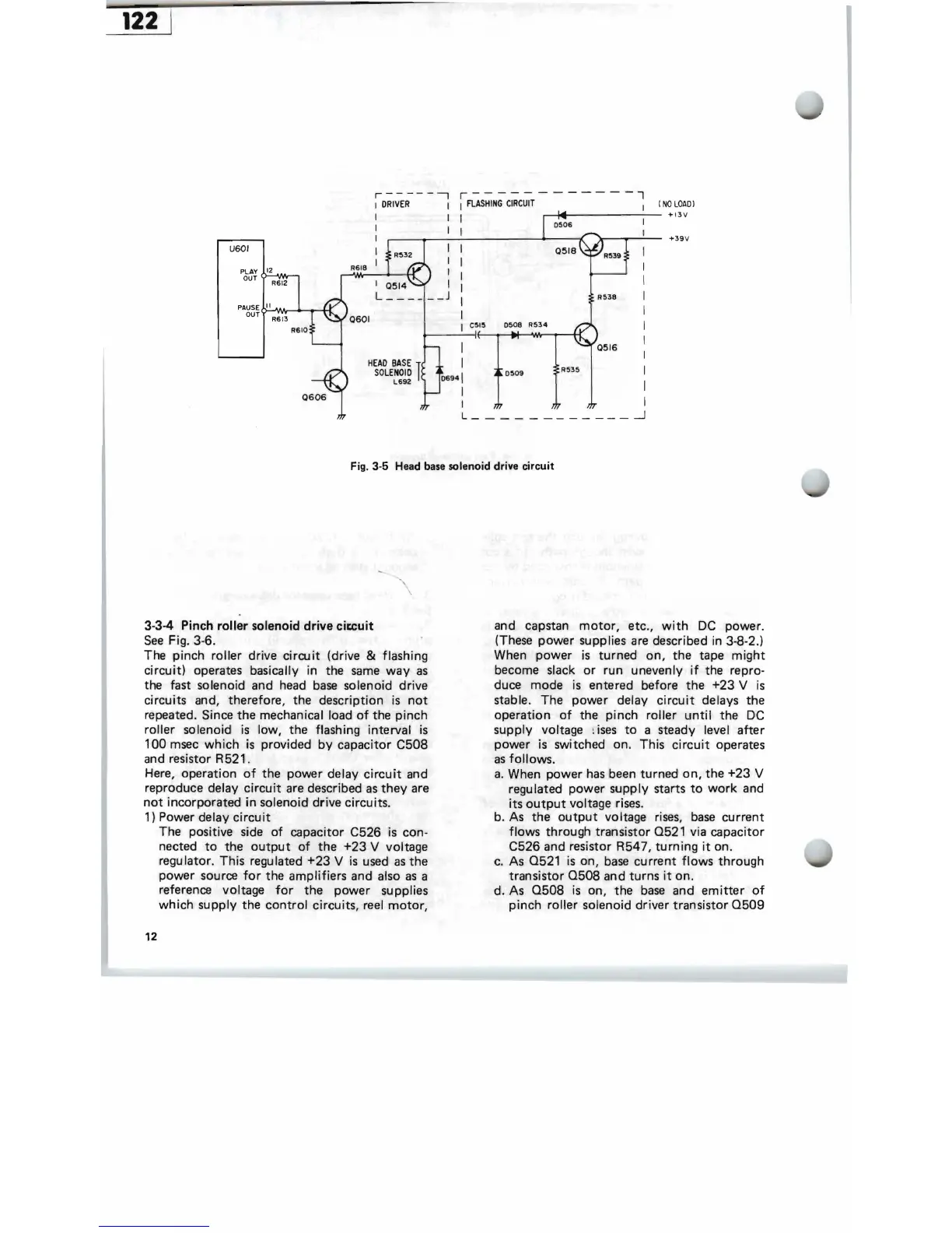
Fig.
3·5
'Head base solenoid drive circuit
3·3-4 Pinch
roller
solenoid
drive
cia:uit
See
Fig. 3·6.
The pinch roller drive
circuit
(drive & flashing
circuit)
operates basically in the
same
way
as
the fast solenoid and head
base
solenoid drive
circuits and, therefore, the description
is
not
repeated. Since
the
mechanical load
of
the
pinch
roller
solenoid
is
low, the flashing interval
is
100
msec
which
is
provided
by
capacitor
C508
and resistor R 521.
Here, operation
of
the power delay
circuit
and
reproduce delay
circuit
are described
as
they
are
not
incorporated
in
solenoid drive circuits.
1) Power delay
circuit
The positive side
of
capacitor C526
is
con·
nected
to
the
output
of
the
+23
V voltage
regulator. This regulated
+23
V
is
used
as
the
power source
for
the amplifiers and also
as
a
reference voltage
for
the
power
supplies
which
supply
the
control
circuits, reel
motor,
12
and capstan
motor,
etc.,
with
DC
power.
(These
power
supplies are described in 3·8·2.)
When
power
is
turned
on,
the
tape
might
become slack
or
run unevenly
if
the repro·
duce mode is entered before
the
+23
V
is
stable. The
power
delay
circuit
delays
the
operation
of
the
pinch
roller
until
the
DC
supply voltage
~
ises
to
a steady level
after
power
is
switched on. This
circuit
operates
as
follows.
a.
When
power
has
been turned
on,
the
+23
V
regulated
power
supply
starts
to
work
and
its
output
voltage
rises.
b. As the
output
voltage
rises,
base
current
flows
through transistor
0521
via capacitor
C526 and resistor R547,
turning
it
on.
c. As
0521
is
on,
base
current
flows
through
transistor
0508
and
turns
it
on.
d. As
0508
is
on, the
base
and
emitter
of
pinch
roller solenoid
driver
transistor
0509


 To Next Page