Do you have a question about the Tascam TM-D8000 and is the answer not in the manual?
Guides on connecting external equipment and making settings.
Explains operations corresponding to analog console functions.
Advises on power supply matching and consulting electricians for doubts.
Outlines common-sense precautions and specific additional recommendations.
Details the correct sequence for powering up studio equipment and TM-D8000.
Deals with keys and indicators for automating mix procedures.
Controls functions like EQ and system parameters, acting as a main control center.
PODs for parameter editing and transport controls for external devices.
Balanced TRS 1/4" jacks used as balanced inputs from line-level sources.
Connects TM-D8000 to a PC via mini-DIN RS-422 for data transmission.
Two connectors for timecode input (XLR balanced, RCA unbalanced).
Balanced XLR jacks accepting various analog signals, with +48V phantom power.
Consists of PODs and switches that change function based on the task.
Guide to connecting external equipment and TM-D8000 functions related to connections.
Describes connection details for analog audio to and from the TM-D8000.
Details the 16 LINE IN 1/4" jacks and their level adjustments.
Details the 16 MIC/LINE XLR connectors and their level adjustments.
Explains how to select analog inputs via the DIGITAL I/O screen after power-up.
Connects DTRS recorders or other TDIF-1 devices as primary recording units.
Explains clock sources (word, video, frame) and indicators.
Explains using TM-D8000 controls (transport, location) to control DTRS units.
Connects TM-D8000 to an Apple Macintosh computer for automation software.
Connects to devices using Sony P2 protocol via RS-422 port for control.
Synchronizes TM-D8000 to external timecode and displays it on the time counter.
Routes signals from D IN connectors to channels or MTR channels.
Connects equipment for synchronization and control purposes, emphasizing clock references.
Details synchronizing to an external source received at the WORD IN connector.
Emphasizes the importance of central house sync for digital audio systems.
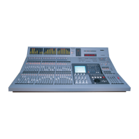
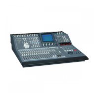
Explains how to use the TM-D8000 as a recording mixing console.
Accepts analog inputs via MIC/LINE XLR and LINE 1/4" jacks for channels 1-16.
Fully-parametric 4-band EQ for all input and MTR channels, and stereo buss.
Provides four fader groups controlled by the fader group section.
Assigns channels to one of four cut groups for muting a group of tracks with one key.
Stores all digital console settings in a snapshot for recall.
Guides setting EQ parameters using the MODULE screen and POD controls.
"Solo safe" channels to prevent muting of other channels during inplace solo.
Controls stereo buss output level and provides more control than analog consoles.
Recalls snapshots from any screen using SNAPSHOT keys.
Edits processor parameters graphically after routing a channel through it.
Sets levels for AUX sends, which are used for effects.
Controls the panning of channel signals.
Solos channels pre-fader or post-fader for monitoring.
Links two channels to treat them as one for stereo sources.
Stores current settings into a snapshot library area from any screen.
Assigns input channels to output busses, stereo buss, or direct out.
Details monitoring of signals and talkback facilities.
Guides multitracking sessions with live talent, focusing on monitoring mixes.
Details the built-in talkback microphone, level control, and routing switches.
Explains how output busses are used for surround channels and recorder feeds.
Allows selection of three surround modes and buss assignment types.
Explains channel distribution across output busses requires more PODs than stereo panning.
Details using on-board controls with external devices for studio operations.
Explains controlling one unit at a time, selecting the unit and degree of control.
Guides on adding and removing devices from the machine control list via AUTO DETECT or manual entry.
Chooses units to be controlled from the list, showing their current control status.
Selects the source of timecode to be displayed on the TM-D8000's time counter.
Configures TM-D8000 for MIDI operations, both as controller and controlled device.
Adjusts track delay, offset, timecode functions, pre-roll/post-roll, and clock source for DTRS units.
Allows setting up to 10 location points for instant recall during a project.
Explains how TM-D8000 transport controls work with other units.
Lists user, confirm, and fatal error messages displayed by the TM-D8000.
Reports unrecoverable software errors requiring a power cycle and reset.
| Type | Digital Mixer |
|---|---|
| Bit Depth | 24-bit |
| Input Types | Analog, Digital |
| Output Types | Analog, Digital |
| Aux Sends | 8 |
| Frequency Response | 20 Hz - 20 kHz |
| Power Supply | AC 100-240V |
| Sampling Rate | 48 kHz |
| Digital Inputs | AES/EBU, S/PDIF |
| Digital Outputs | AES/EBU, S/PDIF |
| EQ | 3-band |
| Automation | Yes |
| Signal-to-Noise Ratio | 100 dB |
| MIDI | In/Out |