4
ASSEMBLY INSTRUCTIONS
1. Top handle
2.
Center handle pieces
3.
Left lower handle
4.
Right lower handle
5.
Foam grip
6.
1-
3/8 in. bolts
7.
Flat washer
8.
Wing nut
Tools Required
Pliers (Not inc
lud
e
d)
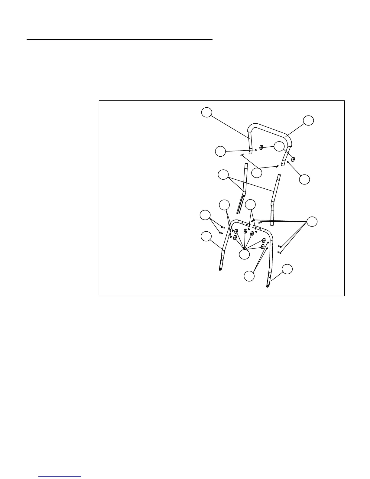
Fig. 1
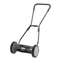
ASSEMBLING THE HANDLE: (Fig.1)
NOTE: Do not completely tighten bolts until assembly is complete.
Before attempting to assemble, empty carton and compare parts with parts list below.
PACKING LIST
1-Top handle,
2-Center handle pieces,
2-Lower handle pieces,
8-Knobs,
8-Bolts,
8-Washers,
1-Reel mower body
Note:
• Carefully remove the parts from the box.
• Inspect the parts to make sure no breakage or damage occurred during shipping.
• Do not discard the packing material until all parts are examined.
• If any parts are damaged or missing, please call 1-800-444-6742 for assistance.
1. Insert the two center handle pieces (2) into the left and right side of the top handle (1) and secure with two
1- 3/8in. bolts (6)
, flat washer (7) and wing nuts (8) provided.
2. Connect the right lower handle (4) with the left lower handle (3) and secure with two 1-3/8in. bolts (6), flat
washer (7) and wing nuts
(8) provided.
3. Attach the top handle subassembly previously assembled, to the lower handle subassembly using four
1-3/8in. bolts (6),flat washer (7) and wing nuts (
8) provided.
4. Tighten all the wing nuts on the joints of the handle assembly.
1
2
3
6
6
6
8
8
7
7
7
7
7
14
4