15
ENGLISH
• COMPATIBILITY WITH OUR APPS: TAUOPEN AND TAUAPP
ATTENTION:
- do not use single cables (with one single wire), ex. telephone cables, in order to avoid break-
downs of the line and false contacts;
- do not re-use old pre-existing cables.
- In case of long sections of cables (> 20 m) for N.O./N.C. controls (e.g. OPEN / CLOSE, STOP, PEDE-
STRIAN, etc.), in order to avoid gate malfunctions, it will be necessary to uncouple the various
controls using RELAYS or using our 750T-RELE device.
2. TESTING
When you have completed the connection:
• All the green LEDs (from 3 to 6) must be on (each of them corresponds to a Normally Closed input).
They go o only when the controls to which they are associated are operated.
• The red opening command LEDs must all be unlit (each corresponding to a Normally Open input)
and illuminate only when the commands they are associated with are given; The green led DL1V
will ash every 4 seconds.
3. TECHNICAL CHARACTERISTICS
Power input to board 230V AC - 50 Hz
Nominal power 400 W
Fast acting fuse for protection of input power supply 230V AC (F1 - 5x20) F 3,15 A
Input voltage of motor circuits 230V AC
Input voltage of auxiliary circuits 24V AC
Fast acting fuse for protection of auxiliary circuits 24V AC (F2 - 5x20) F 500 mA
Working temperature -20°C ÷ +55°C
Box degree of protection IP 44
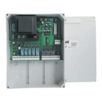
4. TERMINAL BOARD CONNECTIONS
Terminals Function Description
1 - 2 - 3
POWER
SUPPLY
POWER input 230V AC - 50Hz (115V AC - 60 Hz).
1=PHASE 2= EARTH 3= NEUTRAL;
4 - 8 OPEN OPEN pushbutton input (Normally Open contact); (8=COMMON, 4=OPEN)
5 - 8 OPEN/CLOSE
OPEN/CLOSE pushbutton input (Normally Open contact); (8=COMMON,
5=OPEN/CLOSE)
6 - 8 PEDESTRIAN
PEDESTRIAN pushbutton input (Normally Open contact);
NOTE by factory settings the automation will open Equal to one
third of the total strike. (8= COMMON, 6= PEDESTRIAN)
7 - 8 STOP STOP pushbutton input (Normally Closed contact);(8=COMMON, 7=STOP)
9 - 10
SENSITIVE
EDGE
SAFETY EDGE input (Sensitive edge with resistive or N.C. contact). During
the opening phase, it temporarily stops the gate and makes it close again
for about 20 cm, thus allowing to free the potential obstacle.
During the closing phase, it stops the gate and makes it totally reopen. In
this case, if programmed, the automatic closing will be inhibited. Jumper
terminals if not used. (9 = COMMON - 10 = SENSITIVE EDGE)
NOTE: if a resistive sensitive edge 8K2 Ohm is connected, set dip-
switch no. 12 to ON;
If a xed safety edge with NC contact is connected, set dip-switch
no. 12 to OFF;

 Loading...