Section 20H
Section 20H
Heating SystemHeating System
Introduction.Introduction. The heating system provides aThe heating system provides a
comfortable working environment in a cold climatecomfortable working environment in a cold climate
and is essential in removing condensation fromand is essential in removing condensation from
the windshield in which otherwise would impairthe windshield in which otherwise would impair
vision. vision. Provided tProvided the engine-mounted he engine-mounted shut-offshut-off
valves are open, the engine coolant flows throughvalves are open, the engine coolant flows through
the heater coils of the heater / defroster units, airthe heater coils of the heater / defroster units, air
conditioner / heater unit (if equipped), and returnsconditioner / heater unit (if equipped), and returns
back to the engine block.back to the engine block.
Major ComponentsMajor Components(Illustration 20H-2)(Illustration 20H-2).. TheThe
heater system consists of two heater / defrosterheater system consists of two heater / defroster
units, two 30 amp circuit breaker (CB11 andunits, two 30 amp circuit breaker (CB11 and
CB12), air conditioner / heater unit, shut-off valvesCB12), air conditioner / heater unit, shut-off valves
and hoses.and hoses.
Heater / Defroster UnitsHeater / Defroster Units (Illustration 20H-1)(Illustration 20H-1).. TheThe
heater / defroster units are powered by 12 VDCheater / defroster units are powered by 12 VDC
from two 30 amp circuit breaker (CB11 and CB12),from two 30 amp circuit breaker (CB11 and CB12),
employ a two speed switch (S24), two relays (K12employ a two speed switch (S24), two relays (K12
and K13) and are rated at 15,300 BTUs (16,140and K13) and are rated at 15,300 BTUs (16,140
kJ).kJ).
Circuit Breakers.Circuit Breakers. Refer Refer toto Circuit BreakersCircuit Breakersinin
thethe Component TroubleshootingComponent Troubleshootingofof Section 6Section 6
for troubleshooting of circuit breakers.for troubleshooting of circuit breakers.
Shut-off Shut-off ValValvesves (Illustration 20H-2)(Illustration 20H-2).. The The shutoffshutoff
valves [one is located in the air conditioning /valves [one is located in the air conditioning /
heater unit (see Illustration 20A-1) and one isheater unit (see Illustration 20A-1) and one is
engine mounted] control the flow of heated cool-engine mounted] control the flow of heated cool-
ant to the ant to the heater / defroster heater / defroster circuits. circuits. They mustThey must
be fully open be fully open for maximum for maximum operation. operation. If any of If any of thethe
shut-off valves are closed, there will be no flow ofshut-off valves are closed, there will be no flow of
heated coolant to circulate in the heating / defrost-heated coolant to circulate in the heating / defrost-
ing circuit.ing circuit.
Hoses.Hoses. Periodically check Periodically check the hoses the hoses and elbowsand elbows
for chafing for chafing or cracking. or cracking. Replace as Replace as conditionsconditions
require.require.
Severe injury may occur fromSevere injury may occur from
burns. burns. Always shut down Always shut down engine and engine and allow toallow to
cool before servicing or inspecting heatercool before servicing or inspecting heater
hoses.hoses.
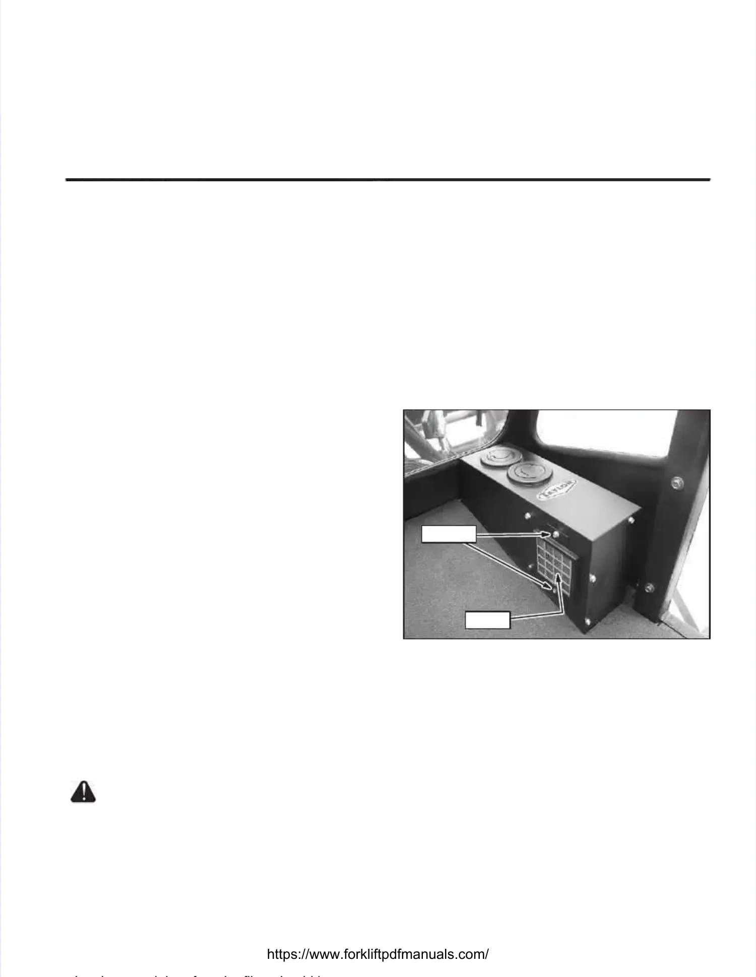
Cleaning and / or Changing The Heater Cleaning and / or Changing The Heater //
Defroster Unit FilterDefroster Unit Filter (Illustration 20H-1)(Illustration 20H-1).. TheThe
heater / defroster unit’s filter should be cleanedheater / defroster unit’s filter should be cleaned
every 3 montevery 3 months or as hs or as conditions warrant. conditions warrant. The fil-The fil-
ter must be replaced once a year or as conditionster must be replaced once a year or as conditions
warrant. warrant. If the filter is If the filter is not cleaned regularlynot cleaned regularly, it , it maymay
become partially clogged with lint, dirt, grease orbecome partially clogged with lint, dirt, grease or
other debris. other debris. A clogged filtA clogged filter will produce er will produce a loss a loss ofof
i l d h f h fil h ld bi l d h f h fil h ld b
cleaned or cleaned or changed. changed. Perform the Perform the following proce-following proce-
dures to remove filters for cleaning or replace-dures to remove filters for cleaning or replace-
ment:ment:
1.1. RemovRemove file filter ter cover cover from from the hthe heater eater / def/ defrosterroster
unit’s housing by removing screws.unit’s housing by removing screws.
2.2. RemRemove fiove filtelter from fr from filtilter cover cover and cler and clean wiean withth
low pressure airlow pressure air. . Replace old filter Replace old filter with newwith new
filter if filter is damaged.filter if filter is damaged.
3.3. InstaInstall filll filter in ter in the fithe filter clter cover aover and snd secuecure tre too
heater / heater / defroster unit with screws.defroster unit with screws.
FILTERFILTER
SCREWSSCREWS
Illustration 20H-1. Illustration 20H-1. Heater / Heater / Defroster Unit Defroster Unit FilterFilter

 Loading...