TX / TXH / TXB 180S - 400L (Rev. 4/23/07)TX / TXH / TXB 180S - 400L (Rev. 4/23/07)
14-614-6
continuously lowcontinuously low
with no signs ofwith no signs of
external leakageexternal leakage
pp pp yy
leaking.leaking.
pp
8.8. GeGear ar oioil ll levevel el inin
hub is continuous-hub is continuous-
ly too highly too high
1.1. SeaSeal bl betwetween een brakbrake he housousing ing andand
wheel hub may be leaking.wheel hub may be leaking.
2.2. CooCoolinling flg fluid puid presressursure is te is too hioo high.gh.
1.1. ReReplplacace se seaeal.l.
2.2. HavHave bre brake ake coocoolanlant prt pressessure ure relreliefief
valve cartridge replaced.valve cartridge replaced.
9.9. SiSigngns os of ef extxterernanall
leakage existleakage exist
1.1. CleClean san surfurface ace and and thethen den deterterminminee
location of leakage.location of leakage.
1.1. ReReplplacace see sealalss..
Section 15
Section 15
Brake Control SystemBrake Control System
Introduction.Introduction. The brake control system controlsThe brake control system controls
the slowing down and stopping of the truck.the slowing down and stopping of the truck.
Hydraulic pressure is controlled by the foot oper-Hydraulic pressure is controlled by the foot oper-
ated brake valves (pedals) and is sent to theated brake valves (pedals) and is sent to the
brake housings of the drive axle to apply the ser-brake housings of the drive axle to apply the ser-
vice brakes. vice brakes. The parking The parking brake control brake control appliesapplies
and releases the spring applied, drive line parkingand releases the spring applied, drive line parking
brake.brake.
Major ComponentsMajor Components(Illustration 15-2)(Illustration 15-2).. The brakeThe brake
control system consists of a main pump, manifold,control system consists of a main pump, manifold,
two accumulators, brake valves, shuttle valve,two accumulators, brake valves, shuttle valve,
drive axle service brakes, parking brake control,drive axle service brakes, parking brake control,
and parking brake. and parking brake. Refer to Refer to the illustrations the illustrations asas
indicated for identification of parts.indicated for identification of parts.
Manifold.Manifold. Refer Refer toto Section 22Section 22for operation offor operation of
the manifold.the manifold.
AccumulatorsAccumulators(Illustration 15-8)(Illustration 15-8).. There There are are twotwo
accumulators connectaccumulators connected to ed to the main the main valve. valve. TheyThey
store a volume of oil at pressure for brake applica-store a volume of oil at pressure for brake applica-
tion. tion. These These accumulators accumulators are are hydro-pneumatichydro-pneumatic
piston type and are precharged with dry nitrogenpiston type and are precharged with dry nitrogen
to 1,250 psi to 1,250 psi (86 bar) and (86 bar) and 500 psi (35 500 psi (35 bar). bar). ReferRefer
toto Section 22ESection 22Efor procedures for checking thefor procedures for checking the
precharge and charging the accumulator.precharge and charging the accumulator.
Brake ValvesBrake Valves(Illustration 15-3)(Illustration 15-3).. There There are are twotwo
brake valves used brake valves used to stop the to stop the truck. truck. Both brakeBoth brake
valves actuate the service brakes of the drive axlevalves actuate the service brakes of the drive axle
when either when either brake pedal is brake pedal is applied. applied. The LH The LH brakebrake
valve can independently disengage the transmis-valve can independently disengage the transmis-
sion (inching) when the brake pedal is applied.sion (inching) when the brake pedal is applied.
When either brake valve is applied, its P and BWhen either brake valve is applied, its P and B
ports will be connected to send hydraulic pressureports will be connected to send hydraulic pressure
to apply to apply the service the service brakes. brakes. When the When the serviceservice
brakes are released, the B port is connected tobrakes are released, the B port is connected to
the T port to vent hydraulic flow back to thethe T port to vent hydraulic flow back to the
hydraulic tank.hydraulic tank.
Inching Operation.Inching Operation. When the When the LH brake LH brake pedal ispedal is
depressed the transmission ill be disengageddepressed the transmission ill be disengaged
parking brake control is pulled out, the hydraulicparking brake control is pulled out, the hydraulic
pressure is released and the parking brake ispressure is released and the parking brake is
applied.applied.
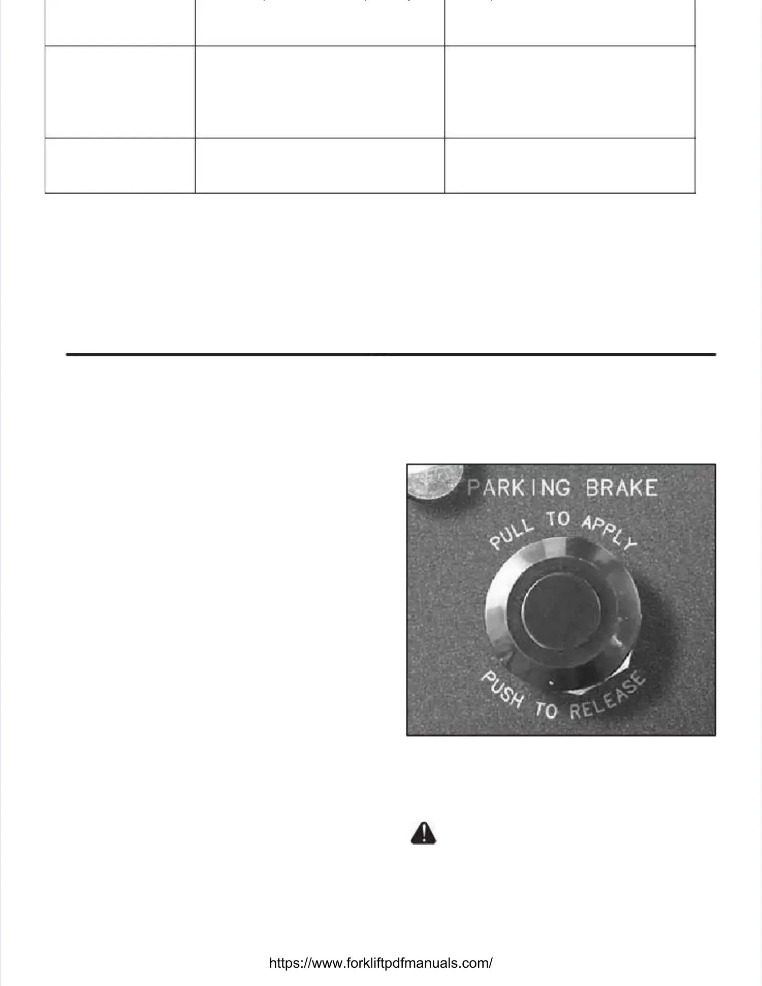
Illustration Illustration 15-1. 15-1. Parking Brake Parking Brake ControlControl
Parking BrakeParking Brake (Illustration 15-4)(Illustration 15-4).. The The parkingparking
brake is spring applied and hydraulically released.brake is spring applied and hydraulically released.
Do not attempt to removeDo not attempt to remove
spring(s), they spring(s), they are not are not serviceable. serviceable. Do not Do not cut,cut,
saw, torch osaw, torch or modify r modify this chamberthis chamber. . SeriousSerious
injury or death could result.injury or death could result.
Parking Brake Linings.Parking Brake Linings. The The parking brakparking brake lin-e lin-
ings should be checked for wear periodically (referings should be checked for wear periodically (refer
to theto the Preventive MaintenancePreventive Maintenance chart in thechart in the
AppendicesAppendicesfor parking brake linings wearfor parking brake linings wear
inspection). inspection). The parking The parking brake linings brake linings should beshould be
replaced before the brake lining friction materialreplaced before the brake lining friction material
 Loading...