Application Hints STV8172A
8/14 STMicroelectronics Confidential
C
S
performs an integration of the parabolic signal on C
L
, therefore the amount of S correction is set
by the combination of C
L
and C
s
.
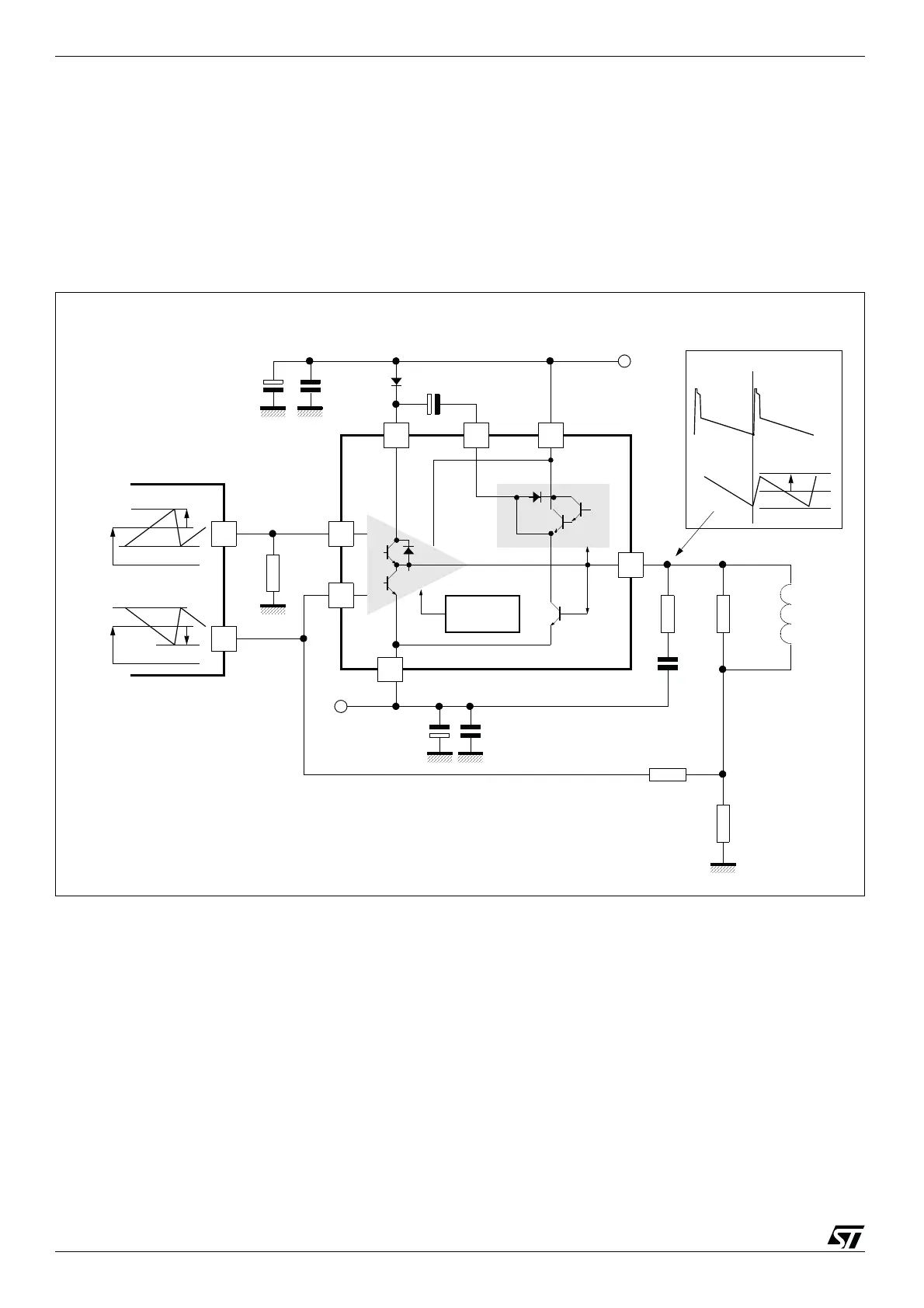
4.3 Application with Differential-output Drivers
Certain driver ICs provide the ramp signal in differential form, as two current sources i
+
and i
-
with
opposite variations.
Let us set some definitions:
● i
cm
is the common-mode current:
● at peak of signal, i
+
=i
cm
+i
p
and i
-
=i
cm
-i
p
, therefore the peak differential signal is i
p
-(-
i
p
)=2i
p
, and the peak-peak differential signal, 4i
p
.
The application is described in Figure 7 with DC yoke coupling. The calculations still rely on the fact
that V
1
remains equal to V
7
.
Figure 7: Using a Differential-output Driver
+Vs
R
2
R
1
Rd(*)
Yo ke
Ly
-V
EE
0.22μF
(*) recommended:
Ly
50m s
--------------Rd
Ly
20m s
--------------<<
0.1μF
0.1μF
C
F
(47 to 100μF)
Power
Amplifier
Flyback
Generator
Thermal
Safety
+
-
470μF
470μF
Output
Current
Output
Voltage
I
p
7
32
5
6
1
4
R
7
+
-
Differential output
driver IC
i
p
i
cm
-i
p
i
cm
1.5W
i
cm
1
2
---i
+
i
-
+()=
 Loading...