408-1610
4 of 11
Rev M
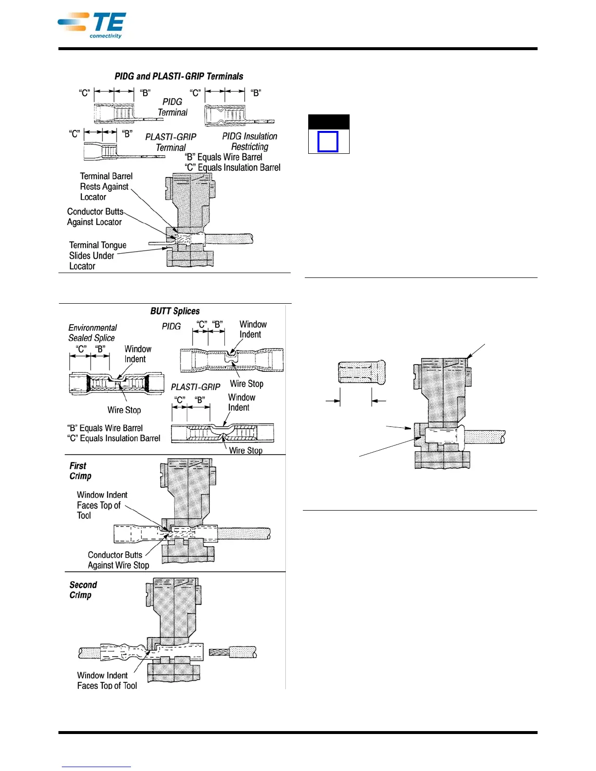
Figure 3
Figure 4
4.2. .Spare Wire Caps
1. Strip wire to dimensions listed in Figure 2. Crimp
the color coded portion of the tool. Refer to
Section 3.
Do not use wire with nicked or missing conductor
strands.
2. Place tool insulation adjustment indicator in
Position 4
.
3. Close tool handles until crimping
jaws partially
close, but leave enough space for cap to be
inserted between dies.
4. Raise locator so that end of cap rests against the
re
cessed surface of the locator as shown in
Figure 5.
Spare Wire Caps
Insulation
Adjustment
Indicator at
Position 4
Wire
Barrel
Locator
Raise Locator So the End
of the Cap Rests Against
the Recessed Surface of
the Locator
Figure 5
5. Squeeze quick take-up trigger and close handles
until cap is held firmly in place. Do not deform cap
wire barrel.
6. Insert stripped wire into cap until conductor
b
ottoms in cap.
7. Hold wire in position an
d complete crimp by
closing handles until the ratchet releases. Handles
will open automatically and crimped cap may be
removed.
8. Refer to Section 6 and Figure 7 wire cap crimp
inspection procedure.