408-1610
5 of 11
Rev M
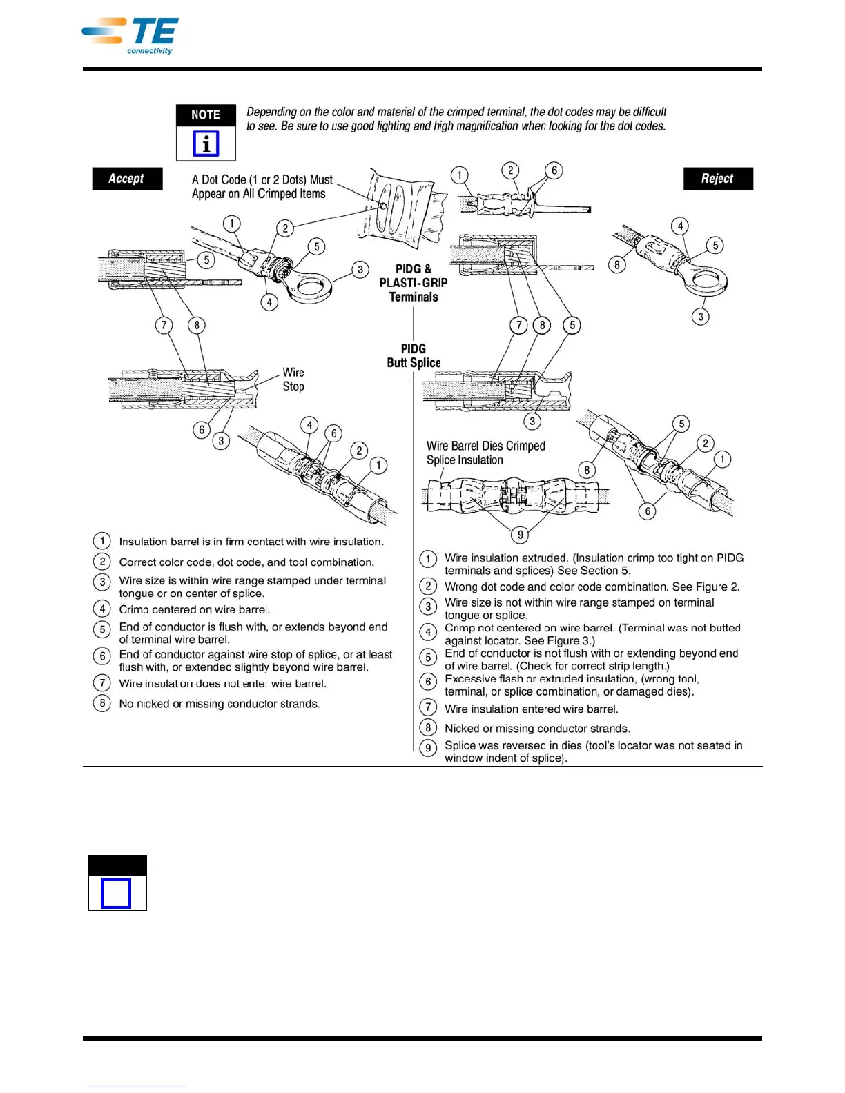
Figure 6
5. INSULATION CRIMP ADJUSTMENT
5.1. PIDG Terminals and Splices
PIDG terminals and splices feature a wire
"insulation grip".
Each tool has four insulation crimp positions. See
Fig
ure 1.
1. Loosen insulation adjustment loc
king screw (see
top of tool) and turn indicator to Position 4.
2. Place terminal or splice in tool dies.
3. Insert UNSTRIPPED wire into ONLY the
insu
lation barrel (see Figure 3 or Figure 4) of
terminal or splice.
4. Perform a crimp (Section 4). Remove crimped
ter
minal or splice and check insulation grip as
follows: Bend the wire back and forth once. Terminal
or splice should retain grip on wire insulation.
5. If wire pulls out, set insulation adjustment
indicator
to next tighter position - Position 3.
 Loading...