408-1610
6 of 11
Rev M
Figure 7
6. Perform a crimp and repeat adjustment as
necessary until desired insulation grip is obtained.
Do not use a tighter setting than required.
7. Tighten insulation adjustment locking screw (see
to
p of tool).
5.2. PLASTI-GRIP Terminals and Splices
PLASTI-GRIP terminals and splices feature a wire
"insulation support" only.
1. Set insulation adjustment indicato
r in Position 4
for wire having a large insulation diameter.
2. Set insulation adjustment
indicator in Position 3
for wire having a medium insulation diameter.
3. Set insulation adjustment
indicator in Position 2
for wire having a small insulation diameter.
4. Set insulation adjustment
indicator in Position 1
for wire having thin wall insulation. Terminal or
splice insulation should ideally be in contact with
wire insulation.
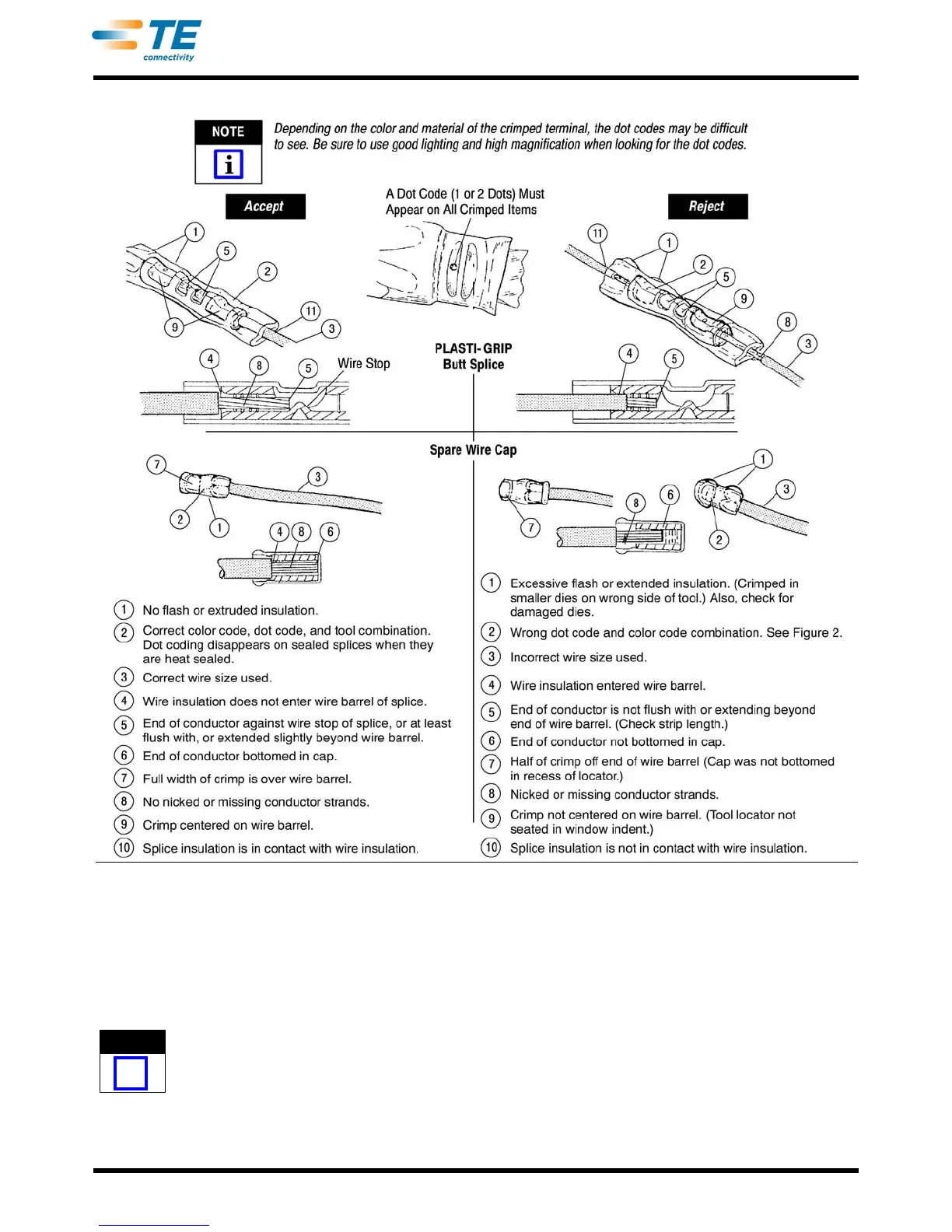
6. CRIMP INSPECTION
Inspect crimped terminals, splices and spare wire
caps by checking the features described in Figure 6 or
Figure 7.
 Loading...