409-10204
Rev G
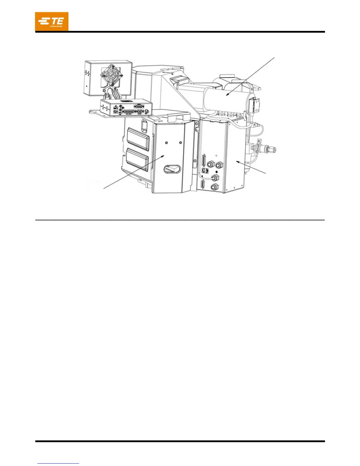
Figure 4
2. The crankshaft-ram group conveys the motor rotational force to the up-and-down action of the ram
for driving the applicator during the crimping cycle.
3. The base plate provides the mounting surface on which the applicator is installed. The quick-release
latching feature permits fast, easy installation and removal of the applicator. See Figure 5.
4. The crimp height adjustment group uses an eccentric located in the ram linkage, along with
detented stops in the mechanism to adjust the crimp height. Indexing the mechanism in either
direction will change the crimp height in increments of approximately 0.013 mm [.0005 in.] per step.
Refer to Figure 5 for the Precision Crimp Height Adjustment Mechanism.
Electrical Control
Box Assembly
Terminal Strip Guide
Mounting Surface for
End-Feed Applicators