23
4 Adjustments
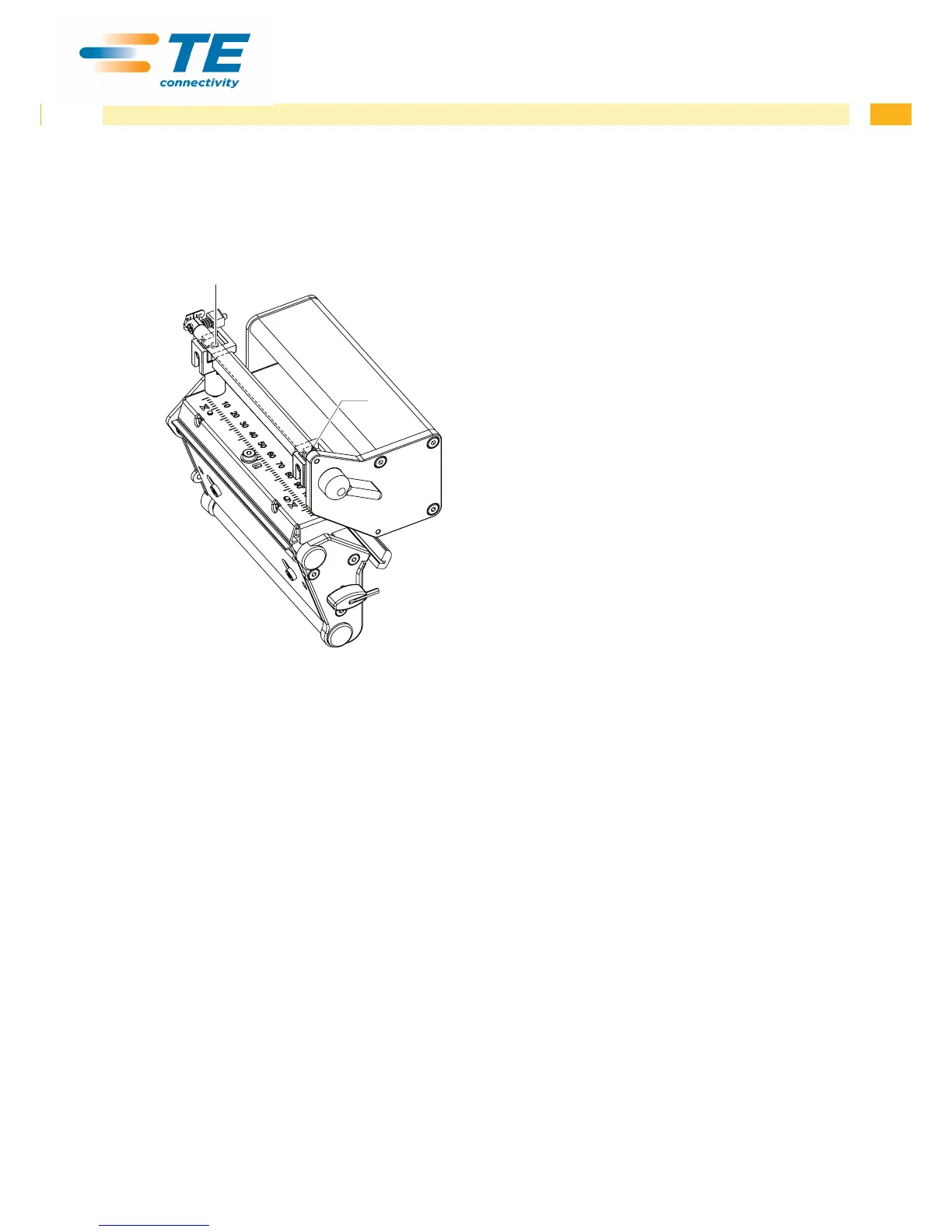
4.2.3 Adjusting the Printhead Pressure
The printhead pressure can be changed with the screws (1a) and (1b) at the inside and outside of the printhead.
Increasing the head contact pressure leads to an improvement of the print image density on the corresponding side
and to a shifting of the ribbon feed path in the corresponding direction.
1a
1b
Fig. 19 Adjusting the printhead pressure
1. Turn the adjustment screws (1) counterclockwise until turning becomes perceptibly easy.
2. The heat level is to be reduced in the printer conguration until the print image is only barely recognizable. Under
these conditions, inaccuracies become clearly visible during adjustment.
3. Create print samples with the test function Test grid or a similar print pattern.
4. Adjust the adjustment screw (1a or 1b) clockwise in small increments on the side with the weaker print image until
the print image is even across the entire width. It may happen that you must turn the adjustment screws in an
alternating fashion, resulting in a print image which is too light overall.
5. For TE3124 /TE3112 printer move the plunger to the printer standard position for the media being printed
operator's manual and repeat the test print. Possibly rerun procedure and adjust again.
6. When the print image is set evenly, continue with setting of the transfer ribbon feed path 4.2.4 on page 24.