Emergency operation]
Manual lowering of the hoist.
Warning: Do not manually lower the hoist unless it is
absolutely necessary as there is a risk that the vehicle
may fall off the hoist if both sides of the hoist are not
lowered evenly.
1. Switch off the isolating switch on the drive column.
2. Measure the height of the drive and slave carriages
and calculate the difference in heights.
3. Put a paint or scratch mark on each screw pulley so
you can count the number of rotations of the pulley.
4a.If two people are available, use 2 large spanners on
the castle nuts on the top of each screw pulley to
wind the hoist down (anticlockwise) making sure that
both pulleys are rotated the same number of turns.
Stop frequently and measure the height of the
carriages and check that the difference in height is
still the same.
Continue until the hoist is fully lowered.
4b.If only one person is available, use a large spanner
on the castle nut on the top of the drive column
screw pulley to wind it down 3 turns only.
(anticlockwise).
Next wind the slave column screw pulley down 6
turns. Next wind the drive column 6 turns. Continue
to wind each column down 6 turns alternately. Stop
frequently and check that the difference in height is
within 20mm of the original difference measurement
(the last carriage wound should be 18mm lower).
Continue until the hoist is fully lowered.
5. Remove the lifting arms from under the vehicle and
remove the vehicle from the hoist.
6. Find and repair the fault that caused the hoist to stop
operating.
Safety devices
This hoist is fitted with a number of safety devices to
protect the operators from injury. These devices must
be fitted and maintained to keep the hoist safe.
Arm locks
The lifting arms are fitted with locks which automatically
engage when the hoist is raised to prevent movement
of the lifting arms or the vehicle if the lifting pads are on
a slippery or sloping surface or the operator is pushing
sideways on the vehicle.
The locks automatically release when the hoist is fully
lowered. They can be manually released by pulling up
on the black knobs.
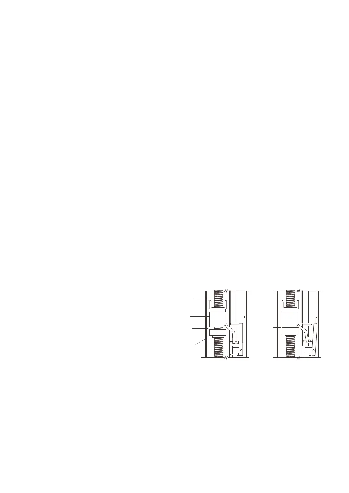
Safety nut and interlock
The lifting nut inside each column (that raises the lifting
arms) is closely followed by a backup safety nut. The
hoist is safe to use while a gap exists between the lift
nut and the safety nut. This gap is visible through the
hole in the column blind when the hoist is fully lowered.
The gap can be measured to determine the amount of
wear in the lift nut so that it can be replaced before it is
completely worn out. If the lift nut is allowed to
completely wear out, the gap between the nuts will
close up completely and the safety nut will carry the
load. This will allow the hoist to be lowered to the floor
safely but a back-up safety interlock device will prevent
the hoist from being raised again until the lift nut is
replaced.
Safety Interlock Mechanism
No gap
between
nuts
Lift Screw
Lift Nut
Gap
between
nuts
Safety nut
Overhead trip bar
A light weight safety trip bar and limit switch is attached
to the overhead cross beam to prevent high vehicles
from colliding with the cross beam and being damaged
or causing damage to the hoist. The trip bar stops the
hoist from raising further but allows it to lower normally.
Page 16
 Loading...