3-1
3-2 3-3
1
1-1
1-2 1-3
2-1
2-2
2
3
System address 1
(Change setting to “1”)
System address 2
(Change setting to “2”) (Change setting to “3”)
System address 3
No. 3No. 2No. 1
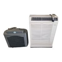
Outdoor unit
Inter-unit control
wiring
Terminal plate 1, 2
Terminal plate 1, 2
Indoor unit
Change the terminal
plug (black) short-circuit
socket
Change the terminal
plug (black) short-circuit
socket
Inter-unit control wiring
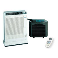
Wired remote
controller
Wireless remote
controller
Wired remote
controller
Remote controller crossover
wiring for group control
Remote controller crossover
wiring for group control
10-26. Automatic Address Setting
10-26-1. Basic wiring diagram
● Link wiring
● A terminal plug (black) is attached to each of the outdoor unit control PCBs. At only 1 outdoor unit, leave the ter-
minal plug short-circuit socket on the “Yes” side. At all the other outdoor units, change the socket (from “Yes” to
“No”).
● A maximum of 8 indoor units can be connected to 1 remote controller for group control.
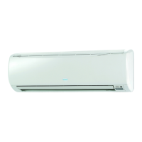
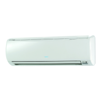
* If wall-mounted type units are used for a simultaneous-operation multi system (group control), refer to 10-16. System Con-
trol (basic wiring diagrams and wiring procedures) on the reverse cover of this manual when wiring.
Fig. 10-25
04-393 DC INV Tech p 64-110 12/13/04 11:35 AM Page 93
 Loading...