Do you have a question about the Technibel CAW Series and is the answer not in the manual?
Symbol for hazards causing severe personal injury or death.
Symbol for hazards causing personal injury or property damage.
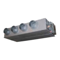
Unit functions include cooling, drying, heating, and fan only.
Identifies the remote control unit and its infrared signal receiver.
Detects ambient room temperature for control adjustments.
Location for room air intake and dust filtration.
Manual mode selection button and status indicator lights.
Mounting brackets, refrigerant couplings, and drain connection.
Avoid locations with fumes, flammable gases, high humidity, or heat sources.
Ensure supply voltage matches unit nameplate and follow local electrical codes.
Proper grounding is mandatory for safe operation.
Read manual carefully; use unit only for its described purpose.
Never store or use flammable vapors or liquids near the air conditioner.
Do not install non-IPX1 protected electrical equipment under the unit.
Manufacturer is not responsible if safety regulations are not observed.
Use remote or unit selector; never the main power switch for start/stop.
Do not insert objects into the air outlet due to high fan speed.
Prevent children from playing with the unit; avoid overcooling for vulnerable individuals.
Instructions for inserting and replacing AAA batteries in the remote control.
Dispose of exhausted batteries according to applicable laws.
Steps to safely remove batteries from the remote control unit.
Choose between remote sensor (I FEEL) and unit sensor for temperature detection.
Unit receives signals on key press or when detected temperature changes.
Turn the unit ON using the ON/OFF button on the remote control.
Shows operating mode, room temperature, and clock status.
Activates remote's internal sensor for precise room temperature control.
Displays indicating timer status and current time on the remote.
Select Cooling, Dry, Auto, or Fan modes using the MODE button.
Control fan speed via the FAN button or automatic microcomputer selection.
Activate rapid cooling/heating (High Power) or energy-saving (Economy) modes.
Use '+' and '-' buttons to adjust the target temperature.
Adjusts the vertical flap position for optimal air distribution.
Buttons for setting clock and ON/OFF timers.
Switches between remote and unit temperature sensors for control.
Steps to set the current hour and minute on the remote control.
Select COOL mode and set the desired temperature using +/- buttons.
Choose the fan speed for cooling operation.
Select HEAT mode and set the desired temperature using +/- buttons.
Choose the fan speed for heating operation.
Explains delayed fan start for Cold Draft Prevention during heating.
Select AUTO mode and set a target temperature range.
Unit adjusts cooling/heating based on perceived temperature, considering humidity.
Select desired fan speed for automatic operation.
Doubles available fan speed, automatically slowing near set temperature.
Specific button presses required to activate this fan speed function.
Select DRY mode and set desired temperature for humidity reduction.
Explains auto cycles, fan speed, and temperature limits for dry mode.
Fan speed is forced minimum, setpoint adjusted automatically in dry mode.
Activates fan-only mode for simple air circulation without temperature control.
Microcomputer automatically adjusts fan speed when AUTO mode is selected.
Manually select desired fan speed using the FAN selector.
Activates the energy-saving mode for reduced power consumption.
Steps to select mode and activate/release the economy function.
Maximizes fan speed for rapid cooling or heating performance.
Room temperature may not match setpoint during high power operation.
Steps to program the unit to turn on at a specific time.
Steps to program the unit to turn off at a specific time.
How to set a daily timer for recurring ON/OFF operation.
Check the set ON/OFF times by pressing the ST button.
Steps to set the unit for one hour of operation at current conditions.
How to cancel the 1 Hour Timer function.
Allows delayed activation of timers for up to 99 days, e.g., after holidays.
Sequence to select timer type, set delay days, and confirm.
Use flaps to control airflow direction based on operating mode.
Recommended flap positions for cooling/dehumidifying (Zone A) and heating (Zone B).
Flap behavior when the unit is off or during heating operation.
Maintenance by trained personnel; disconnect power before cleaning.
Methods for cleaning the unit's exterior casing and grille.
Cautions regarding manual flap adjustment and use of cleaning chemicals.
Steps to detach, clean, and reattach the air intake grille.
How to turn on the unit using the manual operation selector.
How to turn off the unit using the manual operation selector.
Unit stops on power failure and restarts automatically after power is restored.
Steps to detach the air intake grille and remove the air filter.
Guidance on cleaning dust and sticky residue from the air filter.
Detailed procedure for removing the condensate drain pan for inspection or cleaning.
Instructions for reassembling components after drain pan maintenance.
Caution regarding sharp metal edges and heat exchanger vanes during cleaning.
Explains the water level alarm and its system-wide effects when activated.
Avoid blocking air intake/outlet and direct sunlight to conserve energy.
Maintain clean filters, keep openings closed, and ensure adequate room temperature.
Avoid using portable phones near the unit to prevent operational disturbances.
Checks for power, breaker, voltage, operation button, and remote batteries.
Checks for filter cleanliness, heat sources, open windows, obstacles, and temperature settings.
Normal operational sound from plastic parts expanding/contracting with temperature changes.
Defines the meaning of LED ON, OFF, and various flashing patterns.
Conditions for LD1, LD2, LD3 lights during normal unit operation.
Lists errors, corresponding LED status, and resulting system effects.
Clarifies errors like 'Damaged sensor', 'Wrong operating mode', and 'Set temperature not reached'.
Explains the 'Communication Error' for SLAVE units on the SACBUS protocol.
| Brand | Technibel |
|---|---|
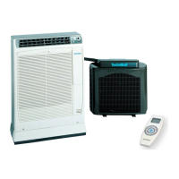
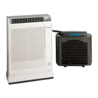
| Model | CAW Series |
| Category | Air Conditioner |
| Language | English |