Ch1
-BRIDGE+
MONO
-BRIDGE+
MONO
Ch2 Ch3 Ch4
OUTPUT
110/220V
220/240V
50-60Hz
AC INPUT
L4Z-4001
INPUT
LIFT
GROUND
STEREO
BRIDGE
MONO
CH1/2
STEREO
BRIDGE
MONO
CH3/4
Ch1
STEREOSTEREO
BRIDGEBRIDGE
MONOMONO
MIXER SPEAKER
Ch3
Ch1 Ch3
Page8
2 Setup
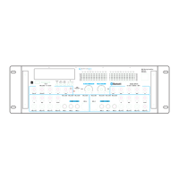
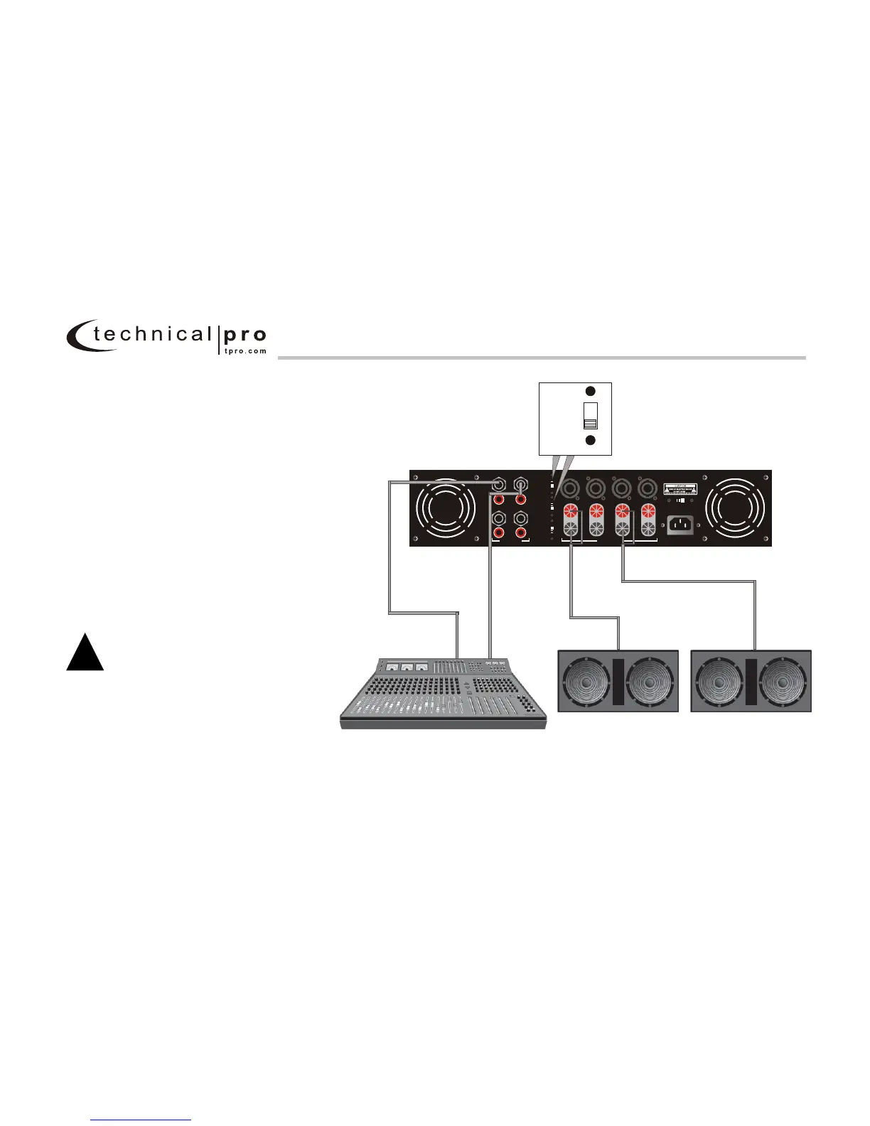
2.6.3 Bridge-Mono Mode
Make sure the amplifier is turned off and the
level controls are turned down before you
wire the system. Make sure the stereo/bridge
switch is set to bridge.
Typical input and output wiring is shown in
Figure 2.6.3.
INPUTS: Connect input wiring to CH.1 and
CH.3. Never used both the RCA and 1/4" jacks
simultaneously on a single channel.
OUTPUTS: When operating the amplifier in
Bridge mode, only the Banana jacks can be
used. In Bridged mode CH.1 and Ch.2 are
combined and CH.3 and CH.4 can be combined.
If the CH.1 and CH.2 are Bridged, than the
banana plug should be connected horizontally,
along the positive jacks of CH.1 and CH.2.
If the CH.3 and CH.4 are Bridged, than the
banana plug should be connected horizontally,
along the positive jacks of CH.3 and CH.4. Refer
to Section 2.5 for output connector pin assi-
gnments. Make sure the Mode switch is set
to the "Bridge Mono" position when operat-
ing in Bridge-Mono mode.
NOTE: Turn down the Channel 2,4 level
control when operating the channel pair
in Bridge-Mono mode, as the Channel 1,3
level control works both channels.
!
Figure 2.6 .3 Typical System Wiring, Bridge-Mono Mode
L - SERIES 4 Way Professional Amplifier