EasyManuals Logo

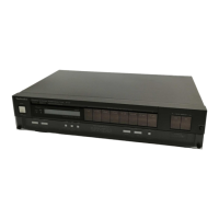
Technics Quartz ST-G7 User Manual

Technics Quartz ST-G7
32 pages
To Next Page IconTo Next Page
To Previous Page IconTo Previous Page
Page #20 background imageLoading...
Page #20 background image
RIS4
33K
—FM
2nd
IF
signal
8.6
A
signal]
REC
input
SWITCH
A
CONTROL
>
NON
DISTORTION
nn
ee
a
Ol,u2a
igeaso
MAI65
VRIO3
5018
a
Pilot
cancel
adj.
Ci3!
20.01
Ol
27
26 25
24
23
21
20
19 18
17
16!
15
Qs
564A
286945
INTEGRAL
.
103
5
.
LOCK
IND.ORIVE
TA
5
/
LOCK
IND.
CONTROL
0401
SVDAY5533K-
M
QUARTZ
INDICATOR
0402
SVDPR5533K
STEREO
INDICATOR
75
kHz
L.P.F.
Qos
2SA995NGF
INTEGRAL
Q109-
2SC1583
INTEGRAL
0106
MAI65
11
12 13
14
Qs
2S8c945
DISTORTION
CONTROL
Qui?
2S¢945
RF
SWITCHING
1€
303,304
MN4066BS
PEAK
SAMPLING
SWITCH/MUTING/
HIGH
BLEND
FM
STEREO
‘2.47
24i2al2aro2
2alza
20720”
1c301
AN7471S
MPXx
28
27
26
25
24
23 22
21
20
19 18
17
16
15
Q50!
2SAS64A
MUTING
CONTROL
1C
305,306
9502,
503
AN6554
OPE
AMP
ascoss
[_[rmyam]
Trm]am]
[FM]
am]
[FM]
am]
|
Fm
[am]
Fitestos
tates
tee
trtos
tos
toloe
fos
tales
tos
Lech
[2.7
|
+
¢
[2.7
| [
2.7
| [
2.7
|
[oo
[10
|
[-2.4
|-8.¢
|
[
0.¢
3
[1.0
|
LPF
LPF
LPF
‘Stereo
LPF
.
>
|
é
co
vco
vcO
Fref
Picn
Picon
LPF
19KMr
PuL_BLL
gut"
ad)
a/m
atop
VEO
cont
[ster
ter
[ele7
er
[ofo*
los
frafos|osl-[-
1—
|
PLL
cain
R+90°
L
L-90°
mute mute
?
Fn”
Poe
vret
“in”
“Spt”
GND
,
SF
OUTPUT
O-~O—@
OOO)
1)
--)
(4)
Rech
Rch
sampling
pulse
°
Input
signal
for
tuner
control
J
>
o>
S064
L—90°
sampling
pulse
FM
mono
distortion
OmV
re
Pilot
cancel
; :
coil
Peak
sampling
switch
5OKB
SIS
bb
—_—
Separation
adj.
.
D710,
712
d
=
5)
SONTROL
Qutput
signal
for
O71
apy
SVDISR35200F
43S
computer
date
SVDMZ303B
RECTIFIER
Al
(s)
A
oath
ars
Ges)
PLI
eobere
(6)
COMPUTER
QUARTZ
RECUCATOR
B
A
INDICATOR
ede
Ne--
PL2
MA4062M_
0712
@)
a
6.2V,
ZENER
LCD
on
Bes
Xo,
aes
2SA564A
C)
cs
REGULATOR
(VOLTAGE
SELECTOR)
(MAIN
POWER)
703
,
35VI000
a+
AC
1107120/220/240V
(50/60
Hz)
0705
MA4I60L
16V,
ZENER
Wald.
Te
igs
Tes
[3
Sy
488
Svoise3sz00F
q
a
+1
2
RS
2SA684
PIR7O8
iy
&
9.
al
RECTIFIER
(11)
REGULATOR
=8
5
5
ie
ds
8
=
i.
RSO!t
560
|
——()
m@
SCHEMATIC
DIAGRAM
(This
schematic
diagram
may
be
modified
at
any
time with
the
development
of
new
technology.)
*
The
part
No.
of
transistors.
|C
and
diodes
mentioned
in
the
schematic
diagram
stand
for
production
part
No.
with
@
mark,
the
production
part
No.
are
dif-
ferent
from
the
replacement
part
No.
Therefore,
when
placing
an
order
for
replacement
part
please
use
the
part
No.
in
the
replacement
part
list.
Note
1:
1.
ST1~S8_:
Preset
tuning
switch.
FM1ch~8ch,
AMQch~16ch.
2.
$9
:
Tuning
(up)
switch.
(manual
auto)
[up:
tuning
to
higher
frequency]
3.
$10
:
Tuning
(down)
switch.
(manual
«>
auto)
[down:
tuning
to
lower
frequency]
4.
$11
:
Memory
switch.
(manual
«+
auto)
5.
$12
:
FM
selector
switch.
6.
$13
:
AM
selector
switch,
7.
$14
:
Recording
level
check
switch.
8.
$15
:
FM
signal
strength
level
call
switch.
9.
$16
:
FM
IF
band
selector
switch.
(normal
«super
narrow)
10.
$17
:
FM
mode
switch.
(auto
«»
mono)
11,
$18
:
FM
muting
switch.
(off
scan
level)
12,
$20
:
Power
switch
in
‘’‘on’’
position.
13,
$21
:
Voltage
selector
switch
in.’’220V"’
position.
110V
«+
120V
«++
220V
«+
240V
14.
$701
:
Main
power
switch
in
‘‘on"
position.
15.
Indicated
voltage
values
are
the
standard.values
for
the
unit
measured
by
the
DC
electronic
circuit
tester
(high-impedance)
with
the
chassis
taken
as
standard.
Therefore,
there
may
exist
some
errors
in
the
voltage
values,
depending
on
the
internal
impedance
of
the
DC
circuit
tester.
*
Figures
in
[____]
stand
for
DC
voltage
in
FM
signal
(monaural)
reception
mode.
*Figuresin?
_)
stand
for
DC
voltage
in
FM
stereo
signal
reception
mode.
*
Figures
in
(
)
stand
for
DC
voltage
in
AM
signal
reception
mode.
*Figuresin
<
>
stand
for
DC
voltage
in
FM-IF
super
narrow
condition
mode.
16.
<—)FM
signal
qoo0oFM
OSC
ea
AM
signal
eneapAM
OSC
AF
signal
lines
17.
Positive
voltage
lines
and
negative
voltage
lines.
18.
Important
safety
notice:
Components
identified
by
A
mark
have
special
characteristics
important
for
safety,
When
replacing
©
any
of
these
components,
use
only
manufacturer's
specified
parts.
19.
The
waveforms
o~
©:
Refer
to
page
17.
Note
2:
©
Use
of
ceramic
filters
in
pairs
The
ceramic
filters
(CF
101
~
CF104)
for
FM-IF
circuit
are
available
in
four
ranks,
For
this
machine,
be
sure
to
use
the
ceramics
of
the
same
rank
in
a
pair.
At
repairing
and
replacement,
pay
close
attention
to
the
diodes
(D901,
D902)
for
use
as
different
diodes
must
be
used
depending
on
each
rank
of
the
ceramic
filters.
sk
ata
(ecian
|
20t
pe02
|
eRFQUENCY
]
,
Black
|
x
oO
10.65
MHz
SFE
|
Red
x
x
10.70
MHz
107
MHz
Blue
O
x
10.67
MHz
Orange
Oo
Hi
O
|
10.73
MHz
Note:
O
Mark
Diode
is
used.
X
Mark
Diode
is
not
used,

Questions and Answers:

Question and Answer IconNeed help?

Do you have a question about the Technics Quartz ST-G7 and is the answer not in the manual?

Technics Quartz ST-G7 Specifications

General IconGeneral
BrandTechnics
ModelQuartz ST-G7
CategoryTuner
LanguageEnglish

Related product manuals