EasyManua.ls Logo

Technics st-ch510

Technics st-ch510
14 pages
To Next Page IconTo Next Page
Loading...
ORDER
NO. AD9407196C8
erviceManual
Tuner/Sound Processor
Tuner
Colour
I(K) Black Type
ST-CH510
System: SC-CH510
Areas
Suffix for
Area Colour
Model No.
(E) Europe
(EG)
Germany and Italy
(K)
Asia, Latin America,
(GC) Middle Near East and
Africa , Oceania
SB-CH510A
/
SB-CH510A
\
I
\ / \
\
\
~\
S
Remote
Control
RS-CH510 SE·CH510
\
\\~\\
Transmitter
~
c..~\
'\i \C L , \" .(.\ -:,
Because
of
unique
Interconnecting
cables
:
~
'
\
\C~
.;\.\\\'"
",c\~:
\'i
when
a
component
requires
service,
send
'J " \
)\",\\
\/~
. \0
or
bring
in
the
entire
system.
.,
-t'
\. (
) .\.\\",.\\'\
I.....
---:
.
~
:::...
-....:.........:;
\.
,
';\\\,- "
, .
,,\c.
C
\' \ ·
\.....----
\X
.(
':'o
"-x
Specifications
""
,:-,
.
270
x89
x274
mm
1.75 kg
MONO
70 dB (75 dB, IHF)
35 dB
75
n (unbalance)
522 - 1611 kHz (9 kHz steps)
530 - 1620 kHz
(10kHz
steps)
144
- 288 kHz (9 kHz steps)
Quarts-lock type
24-hour programmable;
Play timer (1 time) , Rec timer (1 time) ,
Sleep (120 min., 1 min. intervals)
1 minute - 23 hours 59 minutes (1 min. intervals)
SIN
Stereo
separation
1 kHz
Antenna
termlnal(s)
AM tuner section
Frequency
range
MW
Notes:
1. Specifications are subject to change without notice.
Weight and dimensions are approximate.
2. Total harmonic distortion is measured by the digital spectrum
analyzer.
LW
Sensitivity
(SIN 20 dB)
MW
LW
Timer section
Clock
Function
Setting
General
Dimensions
(W x H x D)
Weight
150 mV/1.5
kn
250 mVl15 kQ
250 mV/15 kn
2.5
mVl
47
kn
250 mV/15 kn
30 Hz - 20 kHz
30 Hz
- 20 kHz
87.50 - 108.00 MHz
(0.05 MHz steps)
1.8
uv(IHF usable)
1.
5
11V
200 Hz, 1 kHz. 7 kHz
30 Hz
- 15 kHz/+1.5 to
-2.0
dB
30 H
z-
20 kHz
HALL, HEAVY, CLEAR, CAR. HP ST
Sensitivity
SIN 26 dB
Pre-amplifier section
Input
sens
itivitylimpedance
For
(E)
and
(EG)
areas
PHONO
DCC
For (GC) area
AUX
DCC
Output
level
DCC RECOUT
Frequency
response
For (E)
and
(EG)
areas
PHONO
DCC
For
(GC) area
AUX
DCC
EO,SFP section
Center
frequency
Fixed
mode
5
modes
FMtuner section
Frequency
range
System
Tuner/sound
processor
Compact disc player
Amplifier Cassette Deck
Speakers
SC·CH510
ST-CH510
SL-CH510
SE·CH510
RS·CH510
SB-CH510A
Technics
®
*. For (E), (EG) areas Made in PAES
For (GC) area Made in NABEL
www.freeservicemanuals.info
21/12/2013
Global electronic heritage manuals
Question and Answer IconNeed help?

Do you have a question about the Technics st-ch510 and is the answer not in the manual?

Technics st-ch510 Specifications

General IconGeneral
BrandTechnics
Modelst-ch510
CategoryTuner
LanguageEnglish

Summary

Product Specifications

Pre-amplifier and FM Tuner Specs

Input sensitivity, output level, FM frequency range, and sensitivity.

AM Tuner and System Specs

AM frequency range, S/N, stereo separation, and general system data.

General and Timer Specifications

Dimensions, weight, timer, and clock functionality.

Controls and Time Setting

Location of Unit Controls

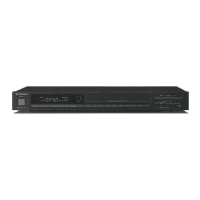
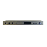
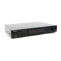
Identifies buttons, sensors, and indicators on the unit.

Setting the Units Clock

Step-by-step guide to set the 24-hour clock and error handling.

Operation Checks and Component Replacement

PCB Checking Procedures

Steps for checking tuner, operation, and main PCBs.

Component Replacement Guidance

Notes on reassembly and screw usage during component replacement.

Schematic Diagrams

Tuner Circuit Schematics

Detailed schematics for tuner circuits in various regions.

Signal and Voltage Convention Explanations

Explanation of symbols for signals and voltages in schematics.

Operation Circuit Details

Circuit Overview and Signal Flow

Description of the operation circuit's signal paths and components.

Technical Notes and Cautions

Important safety and technical notes regarding the operation circuit.

Printed Circuit Board and Wiring Diagrams

PCB Layout Diagrams

Component layout diagrams for Main, Tuner, and Operation PCBs.

Wiring Connection Diagram

Illustration of internal wiring connections between components.

Block Diagram

System Signal Flow and Control Overview

High-level overview of system signal paths and control blocks.

Power Supply and Service Information

ST-CH510 Power Supply Methods

Procedures for powering the ST-CH510 unit for service and testing.

IC Terminal Functions Overview

Pinout and function descriptions for key integrated circuits.

Replacement Parts Lists

IC, Transistor, Diode Parts

Part numbers and descriptions for ICs, transistors, and diodes.

Filter, Oscillator, Switch Parts

Part numbers for filters, oscillators, switches, connectors, transformers, and relays.

Resistor and Capacitor Parts

Detailed lists of resistors and capacitors with part numbers and values.

Cabinet Parts List

Cabinet Component Identification

List of screws, panels, and other cabinet parts with part numbers.

Cabinet Parts Location

Exploded View of Cabinet Parts

Diagram illustrating the physical arrangement of cabinet parts.

Related product manuals