Do you have a question about the Technics ST-G3 and is the answer not in the manual?
Detailed technical specifications for the FM tuner section.
Detailed technical specifications for the AM tuner section.
General technical specifications like output voltage, power consumption, dimensions, and weight.
Procedure to test insulation resistance to prevent electric shock hazards.
Guide on presetting FM/AM broadcast frequencies for quick selection.
Step-by-step instructions for disassembling the unit, including cabinet, front panel, and PCB.
Procedure for adjusting the AM radio frequency (RF) stage.
Procedure for adjusting the FM signal strength level indicator.
Procedure for adjusting FM mono distortion to minimize distortion factors.
Procedure for adjusting stereo separation to ensure optimal channel separation.
Diagram showing the layout of circuit boards and component connections.
Detailed description of the function of each terminal pin of the main control IC.
Guide to terminals for transistors, integrated circuits, and diodes used in the unit.
Overall system block diagram illustrating signal flow and component interaction.
Detailed electronic schematic diagram of the tuner's circuitry.
Exploded view diagram showing component placement for assembly and repair.
| Tuning Range FM | 87.5 - 108 MHz |
|---|---|
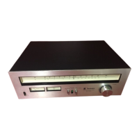
| Tuning Scale | Analog |
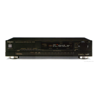
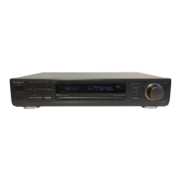
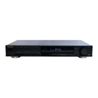
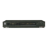
| Type | Tuner |
| Sensitivity AM | 20uV (AM) |
| Signal to Noise Ratio AM | 50 dB |
| Frequency Response | 20Hz to 15kHz (FM) |
| Dimensions | 430 x 265 x 90 mm |