EasyManua.ls Logo

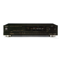
Technics ST-G3

Technics ST-G3
21 pages
To Next Page IconTo Next Page
To Previous Page IconTo Previous Page
Loading...
@
DESCRIPTION
OF
LCD
PANEL
e
COMMON
e
SEGMENT
|
eles
TrTrriy
VDVYVOOVE)
=
aie
TUTTITTEIrrrirrir
OOO
TNIS
HO
OOM
ITINSIES
sy
EEE
SS.
PEEPLP
PEPE
EE
EERE
PEPER
<
Segment
ON
>
Pin
@
or
@
of
LCD
and
each
segment
terminal.
<
Segment
OFF
>
Pin
@
or
@
of
LCD
and
each
segment
terminal.
|
‘ie
2V
AC/DIV,
5m
sec/cm
e
Each
segment
waveform
measuring
method
Note:
Potential
difference
from
COM
terminal
waveform
is
measured
for
each
segment
output
waveform.
So,
do
not
connect
the
earth
to
other
equipment
on
the
oscilloscope
side.
If
the
earth
is
connected,
2V
AC/DIV,
5m
sec/cm
Oscilloscope
Connect
it
to
each
COM
terminal
(probe)
of
1C901.
Connect
it
to
each
segment
terminal
of
1C901.
{C901
will
break
down.
@
TERMINAL
GUIDE
OF
TRANSISTORS,
IC’S
AND
DIODES
2SA564,
250945
2801815
AN7274NS
28Pin
AN7472S-A
HPDITMGSIIA
|
64Pin
SVDKV
12362
MA4062,
MA4082,
MA4150
Al
yy
KI
A2Ke
re
Al
Ki
A2
k2
ST-G3
ST-G3
™@
FUNCTION
OF
TERMINAL
(IC901:
uPD1714G511)
IN/OUT
Description
of
terminal
Ground
terminal.
OUTPUT
Not
used
in
this
unit.
EO2
The
frequency
is
output
as
a
result
of
comparison
between
LCD
frequency
and
FM
or
AM
station
frequency.
Ground
terminal.
(INPUT
AM
Input
for
AM
OSC
output.
1.87V
|
of
(eS
522kHz
1629kHz
Input
for
FM
OSC
output
frequency
divided
to
1/32
or
1/33
by
pre-scaler.
INPUT
cE
Power
supply
detection.
OUTPUT
MUTE
“H”
input
with
it
connected
to
home-use
power
outlet
socket,
H—
4v,
L—O0V
Ground
terminal.
This
is
the
output
terminal
to
eliminate
shock
noise
due
to
unlocking
at
PLL.
4.8V
<Muting
output
>
y
1.
Pin
7
(CE)
is
L—*H
or
H—*L.
a
2.
Power
switch
“off”.
3.
Frequency
change.
(up/down,
FM
«AM,
REC).
4,
FM
IF
selection.
Muting
output
operation
Not
used
in
this
unit.
INPUT
STEREO
H
(4.8V)
—*AM
AM
selector.
Not
used
in
this
unit.
Stereo
indicator
drive.
L
(0)
Stereo
indicator
light
up.
INPUT
sD
OUTPUT
MONO
STANDBY
so
OUTPUT
INPUT
xX
OUT
Xx
IN
26
28
~
39
40
~55
58
INPUT
OUTPUT
OUTPUT
Vpp
Station
detection
1,
Signal
received
—>
H
(5V)
2.
NO
signal
—>L
(OV)
Not
used
in
this
unit.
Forcible
monaural
selection,
4.7V
a
any
Forcible
monaural
mode
Not'used
in
this
unit.
Connecting
terminal
for
crystal
oscillator.
The
crystal
connected
is
at
4.6
MHz.
Power
supply
terminal.
{4,7V)
CGP
$27
~S16
OUTPUT
OUTPUT
iceman
Z
Common
of
LCD.
$15
~
SO
COM
1
Clock
pulse
waveform
output,
Segment
signal
output
for
LCD
display,
LCD
seg
LCD
seg
:
LCD
display
data
KS
:
Key
source
data
INPUT
Vv
DD
Power
supply
terminal,
(4,7V)
59
~62
INPUT
K3
~KO
Input
terminal
for
key
return
signal
from
external
key
matrix.
63
INPUT
SSL
Electromagnetic
field
intensity
level
input
is
changed
from
analog
to
digital.
64
INPUT
Interrupt
requesting
signal
input
terminal.
Band
det.
Signal
from
control
input
terminal
is
put
125
l
J
U
l
into
this
terminal.
Pet
lec
:
,
c
Detected
when
input
is
"L”.
id
18msec
~200msec
get
625msec
580msec

Related product manuals