EasyManua.ls Logo

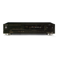
Technics ST-G3

Technics ST-G3
21 pages
To Next Page IconTo Next Page
To Previous Page IconTo Previous Page
Loading...
10
11
12 13
14
15
16
@
SCHEMATIC
DIAGRAM
(This
schematic
diagram
may
be
modified
at
any
time
with
the
development
of
new
technology.)
%
The
part
No.
of
transistors,
IC
and
diodes
mentioned
in
the
schematic
diagram
stand
for
production
part
No.
Regarding
the
part
No.
with
(yr)
mark,
the
pro-
duction
part
No.
are
different
from
the
replacement
part
No.
Therefore,
when
placing
an
order
for
replacement
part
please
use
the
part
No.
in
the
replacement
x
part
list.
c
C309
serves
eke
Note
1:
|
1.
S1~S8
:
Preset
tuning
switch.
1~16
CH
oltage
OmV
Oa
2.
$11
:
Memory
switch,
(manual
<«—®
auto).
3.
$12
:
Tuning
(up)
switch.
[up
:
tuning
to
higher
frequency]
an
4.
$13
:
Tuning
(down)
switch.
[down
:
tuning
to
lower
frequency]
5.
$16
:
FM
selector
switch.
(
—=
frequency
shift
+25
kHz)
_
CONTROLL
INPUT
6.
$17
:
AM
selector
switch.
(
—=
allocation
9
kHz/10
kHz)
Ss
:
.
7.
$18
:
FM
mode
switch.
(auto
«—®
mono).
xt
ST
C303
=
=
Power
source
circuit
8.
$20
:
Scan
level
switch.
(
—dB,
level)
$3
cal
3
g
@
For
[XL]
area
9.
$21
:
FM
signal
strength
indicator
switch.
(off
«—®
on)
zg
:
z
we
wm
a
===>
e——)
&
mentor
e
oie
Seay
Sites
10.
$701
:
Power
source
switch
in
‘‘on”
position.
=a
me
3
|
!
11.
$702
:
Voltage
selector
switch.
THIOL
33K
;
[XA],
[PA]
(110V
«127
V<«—»220V
«—»
240V)
Pees
|
[PE]
and
[PC]
|
;
only
a
12.
Indicated
voltage
values
are
the
standard
values
for
the
unit
measured
by
the
es
i
;
DC
electronic
circuit
tester
(high-impedance)
with
the
chassis
taken
as
standard.
Therefore
there
may
exist
some
errors
in
the
voltage
values,
4
0701
,702
D305
4
se
SVDSR1K2
'
depending
on
the
internal
impedance
of
the
DC
circuit
tester.
MA4082M8e
aaa
}
.
*
Voltage
with
numerical
volume
only
is
the
voltage
with
FM
mono
signal
8.2V
ZENER
©
2
¢
3
|
H
ria
received.
“oS
i
4
25225
:
*
Figures
in
[____]
stand
for
DC
voltage
in
muting
mode.
Oh
t
ie:
.
.
:
Pi
=r
Signal
st
h
level
+
2”
a
(2)
Figures
in
(
)
stand
for
DC
voltage
in
AM
signal
reception
mode.
23
ee
se
bo
e|
Se
tes
|
13,
<==
FM
signal
mana
AM
OSC
u
H
Signal
TSTRENGTH
<a;
<
I
;
;
ere
an
a>
AM
signal
‘AF
signal
lines
oO
2.
CEVEL”
abs
cee
a
8
Ean
CY)
*
[XL]
---
Australia
coon
FM
OSC
———
Positive
voltage
lines.
8
47
Se
ees
3
8l
gh]
ou
soT
14.
Important
safety
notice:
iat
©}
«38
$
é]
3
Seles
ISV
ZENER
op
4
Components
identified
by
A\
mark
have
special
characteristics
important
for
1L80V
ay
@
0926,927
aya}
8
ses
@)
safety.
When
replacing
any
of
these
components,
use
only
manufacturer's
AM
4
MAI65
(3)
specified
parts.
1
«02
<>
1611
|
Refer
to
Note 2
&3
N
2:
kHz
ki
@)
T
ae
re
LL
lote
2:
3)
4
x2
@
.
:
¢
ae
C
|
A e
Use
of
ceramic
filters
in
pairs
_
(|
\
|
MA
Maiso}
ge08
Q701,
@702
S
ce
BACK
UP
(sev
|
C]
f
5
CE
for
EM-IF
=
=
oy
(ND
a
1
1
|
|
fe
]
|
]
1
2
fs
me
2SA564
2SC
1815
maaocem”
|
AMO
Kb
AFI
TS00ma
La
ke
se
220v
The
ceramic
ilters
(C
101,
102)
for
|
circuit
are
available
in
vee
els
“Ato
two
ranks.
For
this
machine,
be
sure
to
use
the
ceramics
of
the
same
rank
Ln
oO
o
.
.
coms
=
roduc
for
ag
3
gh
SH
8
Ina
patr.
Como
4
CxA)
only
FR\e20
ele
oe
At
repairing
and
replacement,
pay
close
attention
to
the
diode
(D901,
seq.0
65)
ee
D902)
for
use
as
different
diodes
must
be
used
depending
on
each
rank
of
sea
69)
2-9)
the
ceremic
filters.
B4V
ee
i
Passa
as
at
ss
&:
inh
ees
if
MATES
o
nn)
17
ar
ape
rom
Color
marking
RANK
CENTER
§
F
3s
ae
@
463+
fn
re
poem"
0
(Red
or
Black)
D
a
3
et
|
£2,
pte
|
sR)
(Color)
FREQUENCY
69
Sn
SN
0216
TT
<2}
Red
Xx Xx
10.70
MHz
D917
>
)
ugI9
Ten
+—+t
al
:
4
al
0920
Ko)
Sasa
lies
Note:
©
=
Mark
Diode
is
used.
o-4
>
rai
19x
|
oe
Ss
Rea
*[XA]
---
Asia,
Latin
America,
Africa,
X
Mark
Diode
is
not
used.
5666.6.56.4
Middle
Near
East
and
Oceania.
*[PA]
---
Far
East
PX.
*[PE]
---
European
Military.
*[PC]
---
European
Audio
Club.
Si
Sia

Related product manuals