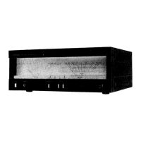
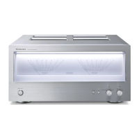
Technics SE-HDA710 Amplifier Service Manual Description
This document is a service manual for the Technics SE-HDA710 Amplifier, part of the SC-HDA710 system. It provides comprehensive information for servicing, maintenance, and understanding the device's functionality and specifications.
Function Description
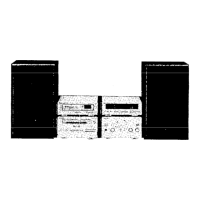
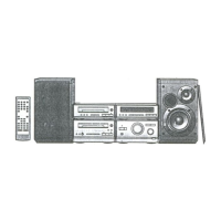
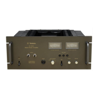
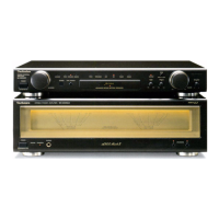
The SE-HDA710 is an amplifier designed to be a core component of the SC-HDA710 system, which includes a Tuner (ST-HDA710), DVD Audio/Video Player (SL-HDA710), Cassette Deck (RS-HDA710), and Speakers (SB-HDA710). The amplifier is responsible for processing and amplifying audio signals across different frequency ranges (low, mid, high) to drive the speakers. It features multiple input selectors, volume control, and fine tweeter control. The system utilizes unique interconnecting cables, emphasizing the need to service the entire system together if any component requires attention.
Important Technical Specifications
The SE-HDA710 amplifier is available in a Gold Type colour and is designed for specific geographical areas: Great Britain (EB) and Europe (EG).
Power Output:
The amplifier's power output is categorized by frequency side:
-
Low Frequency Side:
- DIN 100Hz, THD 1%, 4Ω, both channels driven: 2x12W
- RMS 100Hz, THD 10%, 4Ω, both channels driven: 2x15W
- Load impedance: 4Ω
-
Mid Frequency Side:
- DIN 1kHz, THD 1%, 8Ω, both channels driven: 2x8W
- RMS 1kHz, THD 10%, 8Ω, both channels driven: 2x10W
- Load impedance: 8Ω
-
High Frequency Side:
- DIN 10kHz, THD 1%, 4Ω, both channels driven: 2x4W
- RMS 10kHz, THD 10%, 4Ω, both channels driven: 2x5W
- Load impedance: 4Ω
Total Harmonic Distortion:
- Half power at 1kHz 8Ω: 0.09%
Signal-to-Noise Ratio (S/N):
- S/N: 81dB
- S/N (2V Input, Rated power output): 100dB
Headphones:
- Jack type: 3.5mm STEREO
- Load impedance: 16-32Ω
General Specifications:
- Power consumption: 115W
- STANDBY condition: Normal: 11W, Eco: 0.9W
- Power supply:
- For (EG) area: AC230V, 50Hz
- For (EB) area: AC230-240V, 50Hz
- Dimensions (WxHxD): 196x105.8x261mm
- Weight: 3.6kg
Notes on Specifications:
- Design and specifications are subject to change without notice.
- Dimensions and weight are approximate.
- Total harmonic distortion is measured by a digital spectrum analyzer.
Usage Features
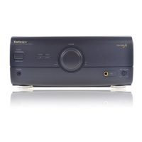
The amplifier features a front panel with various controls and indicators, including:
- Standby indicator
- Standby/On switch
- Eco mode button (MODE)
- Input selector buttons (INPUT SELECTOR ▲/▼)
- Volume control (VOLUME)
- BLFS button (BLFS)
- Fine tweeter control (FINE TWEETER CONTROL)
A remote control transmitter (RAK-HDA37WH) is included, offering comprehensive control over the amplifier and other system components. Remote control functions include:
- Power button
- Sleep timer button (SLEEP)
- Numbered buttons
- Top menu/subtitle button (TOP MENU, SUBTITLE)
- Menu button (MENU)
- Marker button (MARKER)
- Audio/angle button (AUDIO, ANGLE)
- Play mode select button (PLAY MODE)
- Repeat/A-B repeat button (REPEAT, A-B REPEAT)
- Muting button (MUTING, MULTI)
- Shift button (SHIFT)
- Display button (DISP)
- Cancel button (CANCEL)
- Group/time search button (GROUP, TIME SEARCH)
- Cursor/enter buttons
- Return button (RETURN)
- Stereo/mono button (AUTO/MONO)
- On screen display/set up button (OSD, SET UP)
- Input select buttons
- MD/CD, TAPE, EXT/MD, TUNER
- Basic operating buttons
- MD deck operations (when connected to MD deck SJ-HDA710)
- Search/page button (◄◄ SLOW/SEARCH ►►, -PAGE+)
- Volume/balance control (VOLUME+, VOLUME-, BALANCE L, BALANCE R)
For normal operation, the SE-HDA710 must be connected to the ST-HDA710 Tuner via a connection cable. The manual outlines the steps for connecting the tuner, AC mains lead, and speakers, then powering on the amplifier, selecting an input source, and confirming sound output across all frequency ranges ("High", "Mid", and "Low").
Maintenance Features
The service manual provides detailed instructions for repair and adjustment, emphasizing safety and proper procedures.
Safety Precautions:
- For United Kingdom (EB area code model only): Detailed instructions for mains plug safety, fuse replacement (5-ampere, ASTA or BSI approved to BS1362), and wiring code for new plugs (Blue: Neutral, Brown: Live). It warns against connecting wires to the Earth terminal and states the plug is not waterproof.
- General Warning: Service information is for experienced repair technicians only. Products powered by electricity should only be serviced by professionals to avoid serious injury or death.
- Protection Circuitry: The amplifier includes protection circuitry to prevent damage from shorted speaker wires or incorrect speaker impedance. If no sound is heard or sound stops, the user should press the STANDBY/ON button to switch to standby, identify and correct the problem, then press STANDBY/ON again.
- AC Main Lead Caution: Not specified in detail, but highlighted as an important section.
- Important Safety Notice (Schematic Diagram Notes & Replacement Parts List): Components identified by a specific mark have special characteristics important for safety. Special parts (fire-retardant resistors, high-quality sound capacitors, low-noise resistors) must be replaced with manufacturer-specified parts.
Before Repair and Adjustment:
- Power Discharge: Turn off the power supply. Use a 10Ω, 10W resistor to discharge the voltage across power supply capacitors (C102-105, 127).
- Power Supply Check: Before turning the power supply on after repair, slowly apply primary voltage using a power supply voltage controller. Verify that the consumed current in NO SIGNAL mode is within the specified range for the supply voltage (AC 230V/240V, 50Hz, 90-180 mA).
Operation Checks and Component Replacement Procedures:
The manual outlines procedures for checking and replacing components on major printed circuit boards (PCBs). For reassembly, reverse the disassembly steps. Special reassembly procedures are noted when required.
- Checking Power Supply (1) P.C.B., Power Supply (2) P.C.B., and Speaker Terminal P.C.B.: Involves removing the cabinet (Step 1-3) and then checking the specified PCBs.
- Checking Operation P.C.B.: Requires following the initial steps for cabinet removal, then releasing claws to remove the front panel assembly and checking the Operation P.C.B.
- Checking Main P.C.B.: Involves removing the power supply (2) P.C.B., releasing claws to remove the rear panel, and checking the Main P.C.B. A note advises insulating the Main P.C.B. with insulation material to avoid short-circuiting.
- Replacement for the Power IC: This is a multi-step process involving removal of connectors, the main P.C.B., power supply (1) P.C.B., speaker terminal P.C.B., and the fan. Finally, the power IC is unsoldered. A crucial note states that silicone compound (RFKX0002) must be applied to the rear side of the power IC when mounting it.
Schematic Diagram Notes:
- The schematic diagrams may be modified with new technology.
- Voltage values are standard DC values measured with a high-impedance tester, and slight errors may occur.
- Components with a specific mark are safety-critical and must be replaced with specified parts.
- Resistors for fire-retardant purposes, capacitors for high-quality sound, and resistors for low-noise are examples of special parts.
Replacement Parts List:
The manual includes a detailed list of replacement parts, including part numbers, descriptions, and remarks. It specifies that only manufacturer-specified parts should be used. Indications in the remarks column (e.g., "", "", "", "") refer to language versions of instruction manuals. The "RTL" mark indicates a retention time for items, after which they may no longer be available. Remote control assemblies have a supply period of three years from terminal of production. Capacity values are in microfarads (uF) unless specified otherwise. Resistance values are in ohms, unless specified otherwise, 1K=1,000 (OHM), 1M=1,000K (OHM).
Cabinet Parts Location and Packaging:
Diagrams illustrate the location of cabinet parts and the packaging method for the entire SC-HDA710 system components.