Do you have a question about the Technics SE-HD81 and is the answer not in the manual?
Details power output, harmonic distortion, load impedance, and S/N ratio.
Covers power consumption, supply voltage, dimensions, and weight.
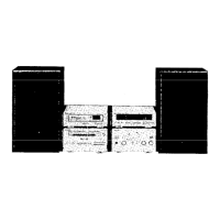
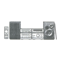
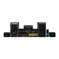
Lists included accessories like power cords, remote controls, and cables.
Safety instructions for AC power cord/plug and fuse replacement.
Explains the protection circuit and troubleshooting steps.
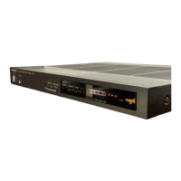
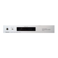
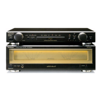
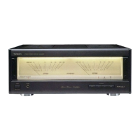
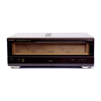
Identifies and describes the function of each control on the amplifier unit.
Guides on setting up and connecting system components.
Step-by-step guide on connecting cables, antennas, and speakers.
Adjusts bass, treble, vocal presence, and source direct modes.
Details features like volume muting via remote or amplifier.
Outlines steps for checking operation and PDM printed circuit boards.
Instructions for replacing specific components like the regulator transistor.
Detailed schematic of the operation circuit, including tone and mode controls.
Schematic for the headphones jack and associated circuitry.
Schematic of the PDM circuit, related to signal processing.
Schematic for the main processing and control circuits.
Schematic of the power supply section, showing voltage regulation.
Schematic for input/output connectors and terminal interfaces.
Schematic of the power transformer and its connections.
Schematic for the AC input terminal and related safety components.
Diagram showing layout and component placement for the Operation PCB.
Diagram showing layout and component placement for the Headphones Jack PCB.
Diagram showing layout and component placement for the Power Supply PCB.
Diagram showing layout and component placement for the Main PCB.
Diagram showing layout and component placement for the In/Out Terminal PCB.
Diagram showing layout and component placement for the PDM PCB.
Diagram showing layout and component placement for the Power Transformer PCB.
Diagram showing layout and component placement for the AC In Terminal PCB.