Do you have a question about the Technics SE-CA10 and is the answer not in the manual?
Covers DIN, RMS power output and total harmonic distortion (THD) for various configurations.
Details power consumption, supply voltage, dimensions, and unit weight.
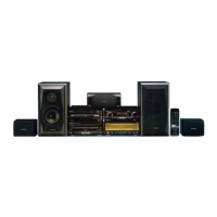
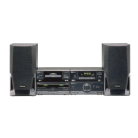
Lists system components and explains regional area codes and color variants.
Lists included power cords, speaker cords, and flat cables for system setup.
Details remote transmitters and indoor antennas supplied with the system.
Mentions batteries and optional power plug adapters for regional compatibility.
Instructions for safely discharging power capacitors before performing service.
Procedure for checking consumed current upon initial power-up after repair.
Explains the protection circuitry function and steps to reset it.
Specific safety instructions and fuse replacement details for the AC power cord in the EB region.
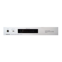
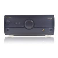
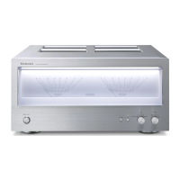
Identifies and describes the function of each control on the front panel.
Details controls like Center Mode, Bass, and Treble on the rear panel.
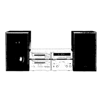
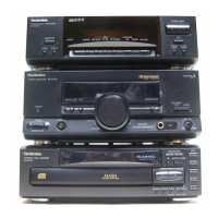
Describes horizontal and vertical stacking options for system components.
Recommendations for optimal positioning of front, center, and surround speakers.
Instructions for connecting system components using the included flat cables.
How to connect AM and FM antennas to the tuner unit.
Detailed steps for connecting front, surround, and center speakers to the amplifier.
Specifics on connecting the main AC power cord to the unit and outlet.
Guidance for connecting external FM/AM antennas for improved reception.
Connecting TVs, VCRs, Laser Disc Players, and Video Cassette Recorders to the system.
Instructions for using a 21-pin SCART cable for connections.
Connecting analog turntables and digital CD changers to the system.
Details for connecting digital audio sources using optical fiber cables.
How to use SURROUND and 3 STEREO modes with various speaker configurations.
Adjusting center speaker mode (NORMAL, WIDE, PHANTOM) based on speaker size.
Using test signals and remote control for precise speaker level balancing.
Setting surround speaker delay time based on speaker distances for optimal effect.
Switching input sources (TUNER, CD, TAPE, etc.) for surround modes.
Procedures for checking the operational status of printed circuit boards.
Introduction to main component replacement based on part numbers.
Steps for removing and replacing the power IC and regulator transistors.
Detailed steps for removing and replacing the meter unit assembly.
Procedures for replacing unit feet and checking power on/off operation.
Steps to calibrate the power meter by adjusting VR808 and VR809.
References to specific schematic sections like Operation, Main, Power Transformer, etc.
Safety precautions regarding IC/LSI handling and component replacement.
Details of the operation circuit including tone amp, muting, and signal selector.
Schematic diagram for the headphones output path and related components.
Schematics for volume, tone controls, LED drive, and relay control.
Diagrams illustrating speaker drive signals and relay activation circuitry.
Schematics for the main power amplifier circuits and associated components.
Diagrams related to overload detection, protection logic, and control circuits.
Schematics of the power transformer, AC input filtering, and power distribution.
Visual representation of component locations on the main printed circuit board.
Layouts for the operation, headphones jack, and power supply PCBs.
Layouts for the power transformer, AC terminal, and voltage selector PCBs.
Pin identification guides for integrated circuits, transistors, and diodes.
Diagram showing how major PCBs and units are interconnected.
Functional blocks and signal flow for audio processing and controls.
Block representation of power supply distribution and output circuitry.
Detailed functional blocks for meter drive, headphones amp, and power amplifier stages.
Exploded views showing the location of chassis parts and internal components.
List of screws, flat cables, chassis parts, and holders for the unit's structure.
List of integrated circuits (ICs) used for audio processing and system control.
List of transistor types and their corresponding part numbers.
List of diodes, LEDs, switches, connectors, and jacks used in the unit.
List of fuses, fuse holders, and power transformers with their part numbers.
Part numbers and values for resistors R223 through R561.
Part numbers and values for resistors R562 through R888.
Part numbers and values for capacitors C251 through C516.
Part numbers and values for capacitors C551 through C906.
Visual guides showing how to pack the tuner, cassette deck, CD changer, and system.
| Total Harmonic Distortion | 0.08% (20Hz-20kHz, 8Ω) |
|---|---|
| Frequency Response | 20Hz - 20kHz (+0dB, -3dB) |
| Input Sensitivity | 500mV |
| Signal-to-Noise Ratio | 80dB |
| Impedance | 6 ohms |
| Type | Stereo Amplifier |
| Output Power | 100W + 100W (8Ω, 20Hz-20kHz, 0.08% THD) |