Do you have a question about the Technics SE-A5MK2 and is the answer not in the manual?
Detailed technical specifications for the amplifier's performance parameters.
Overall product specifications including power, dimensions, and weight.
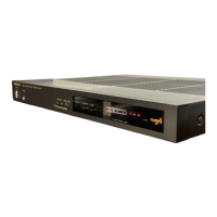
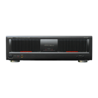
Description of input/output terminals and selectors on the rear panel.
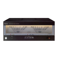
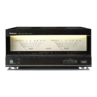
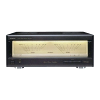
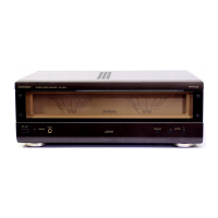
Identification and function of controls and indicators on the front panel.
Procedure for testing insulation resistance to prevent electrical shock hazards.
Step-by-step guide for safely removing the main unit cabinet.
Procedure for detaching the front panel assembly from the chassis.
Instructions for removing the bottom board assembly from the unit.
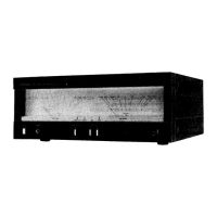
Steps to safely detach and remove the peak power meter assembly.
Detailed procedure for removing the power output transistors from the heatsink.
Procedure for setting the quiescent current (ICQ) for optimal performance.
Steps to calibrate the peak power meter for accurate readings.
List of resistor types, values, wattage, and tolerances.
List of capacitor types, values, voltage, and tolerances.
Diagram showing component placement on the Peak Power Meter PCB.
Component layout for the Signal Detection and ICQ Control PCB.
Diagram of component placement on the Headphones Terminal PCB.
Component layout for the Power Supply and Meter Drive PCB.
Component layout for the Power Amp and ICQ Control PCB.
Component layout for the Differential Amp and Pre-Drive Amplifier PCB.
Component layout for the Input Selector PCB.
Component layout for the Speaker Selector PCB.
Component layout for the Speaker Terminal PCB.
Detailed functions of ICQ control terminals and their signal descriptions.
Explains how signal and temperature affect ICQ control.
Details the overload detection mechanism and its impact on ICQ.
Explains voltage control based on current detection for power transistors.
| Type | Stereo Power Amplifier |
|---|---|
| Frequency Response | DC~300kHz +0dB -3dB |
| Total Harmonic Distortion | 0.007% (8 ohms, 20Hz-20kHz) |
| Input Sensitivity | 1V/47k ohms |
| Dimensions | 420 x 130 x 375 mm |
| Weight | 12 kg |
| Damping factor | 100 (8Ω, 1kHz) |
| Input Impedance | 47k ohms |
| Speaker load impedance | 4 ohms ~ 16 ohms |