Do you have a question about the Technics SE-CH530 and is the answer not in the manual?
Specifies power output in Watts (RMS/DIN) for different regions and load impedances.
Details total harmonic distortion ratings at rated and half power.
Instructions for safely discharging capacitors and checking voltage before initial power-up.
Explains protection circuit triggers (no sound, stops) and the reset procedure.
Specific safety warnings for the AC mains lead in the EB area.
Step-by-step instructions for safely replacing the fuse in the plug.
Warnings against connecting/disconnecting cables while the unit is powered on.
Warning to use only recommended speakers to prevent unit damage.
Steps for checking the operational status of printed circuit boards.
Overview of procedures for replacing major internal components.
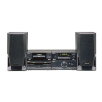
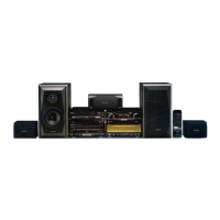
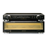
This service manual provides comprehensive information for the Technics SE-CH530 Amplifier, a key component of the SC-CH530 mini-system. Designed for experienced repair technicians, it details the amplifier's functions, usage, and maintenance procedures, ensuring proper servicing and longevity of the device.
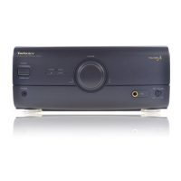
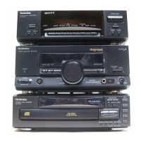
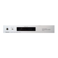
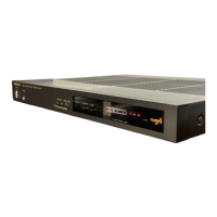
The Technics SE-CH530 is an amplifier unit, responsible for boosting audio signals to drive speakers. As part of a modular mini-system, it integrates with other components like a tuner/sound processor (ST-CH530), compact disc player (SL-CH530), and cassette deck (RS-CH730). The amplifier features multiple input options to accommodate these various sources, processing audio signals for optimal sound reproduction.
Key functional controls include a "STANDBY/ON" switch for power management, a standby indicator, and a volume control for adjusting output levels. For enhanced audio customization, the amplifier incorporates a "SOURCE DIRECT" button, an "EQ SPACE/FLAT" button, and a "V. BASS" button, allowing users to tailor the sound to their preferences. It also includes a headphones jack for private listening and a microphone jack with an associated volume control for microphone input.
The amplifier's internal circuitry is designed with safety and performance in mind, featuring a protection circuit that safeguards against damage from shorted speaker wires or incorrect speaker impedance. This protection circuitry ensures that the unit will not operate under hazardous conditions, requiring a power cycle to reset once the issue is resolved.
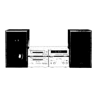
The SE-CH530 is designed for ease of integration within the SC-CH530 mini-system. Its modular design allows for flexible stacking configurations, either horizontally or vertically, to suit different user setups. Unique interconnecting flat cables facilitate seamless communication between the amplifier and other system components. These cables are designed for secure connection, with recessed parts that click into place, and are intended to be folded flat against the back of the unit to minimize noise pickup, especially during AM broadcasts.
Connecting the amplifier to speakers is a straightforward process, but requires attention to detail to prevent damage. Users are instructed to strip and twist speaker cable ends, ensuring no stray wires, and to securely insert them into the speaker terminals, matching positive and negative connections. The manual emphasizes the importance of using recommended speakers with an impedance of 6-8 ohms to avoid damage and potential fire risks.
For external audio sources, the amplifier provides various connection options. It can connect to a DCC or mini disc player via "REC PLAY" (IN/OUT) terminals and to a tuner/sound processor via "EXTERNAL OUT/IN" terminals. For analog players, specific "PHONO OUT" and "LINE OUT" connections are available, with a "GND" terminal for ground wire use, particularly for models in Continental Europe. The manual specifies that only analog players with a built-in phono equalizer can be connected to certain models, highlighting regional variations in connectivity.
Antenna connections are also detailed, with instructions for connecting FM indoor and AM (MW/LW) loop antennas to the tuner/sound processor. The manual provides guidance on optimizing antenna placement for best reception, including recommendations for outdoor antennas in challenging signal areas. For the FM indoor antenna, users are advised to ensure the wire tip does not contact metal objects.
The service manual is primarily a maintenance guide, offering detailed procedures for checking and replacing components. It stresses the importance of safety, particularly when dealing with electrical products, and advises that only experienced professional technicians should attempt repairs.
Before any repair, technicians are instructed to turn off the power supply and discharge power supply capacitors using a resistor to prevent electrical shock. A critical pre-repair check involves monitoring the consumed current at 50/60 Hz in NO SIGNAL mode, ensuring it falls within specified ranges (60-200 mA for 230V/240V AC supply).
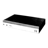
The manual provides step-by-step instructions for disassembling the unit, including removing the cabinet and accessing the printed circuit boards (P.C.B.s). Illustrated diagrams show the location of screws and components, aiding in efficient and accurate repair. Procedures for checking the operation of the main P.C.B. and the operation P.C.B. are outlined, along with instructions for reassembly.
For component replacement, specific guidance is given for power ICs and regulator transistors. Technicians are advised to apply silicone compound to the rear side of these components during mounting to ensure proper heat dissipation. The manual also includes a comprehensive replacement parts list, identifying components with special safety characteristics (marked with a triangle) that require specific manufacturer-specified parts for replacement. These special parts include fire-retardant resistors, high-quality sound capacitors, and low-noise resistors, all crucial for maintaining the device's safety and performance.
The manual also highlights precautions regarding static electricity, advising technicians to ground soldering irons, use conductive mats, and avoid direct finger contact with IC and LSI legs to prevent damage. This meticulous attention to detail ensures that maintenance is performed safely and effectively, preserving the integrity and functionality of the Technics SE-CH530 amplifier.
| Type | Stereo amplifier |
|---|---|
| Power Output | 40 watts per channel into 6Ω (stereo) |
| Frequency Response | 20Hz to 20kHz |
| Total harmonic distortion | 0.8% |
| Input Sensitivity | 3mV (MM), 200mV (line) |
| Dimensions | 270 x 118.5 x 336mm |
| Weight | 5.5kg |
| Speaker load impedance | 16 ohms |