EasyManua.ls Logo

Technics SE-CH505A User Manual

Technics SE-CH505A
22 pages
To Next Page IconTo Next Page
Page #1 background imageLoading...
Page #1 background image
ORDER
NO.
AD9309272C2
Service
Manual
Amplifier
Remote
Control
Transmitter
SL-CH505
ST-CH505
SB-CH515A
RS-CHS505
SE-CH505A
Because
of
unique
interconnecting
cables,
when
a
component
requires
service,
send
or
bring
in
the
entire
system.
Specifications
Power
output
DIN
1
kHz,
THD
1%,
both
channel
driven
2x50
W
(6Q)
Total
harmonic
distortion
Rated
power
at
1
kHz
1%
(6Q)
Half
power
at
1
kHz
0.09%
(6Q)
Load
impedance
MAIN
6~80
SURROUND
8Q
S/N
(rated
power)
84
dB
Frequency
response
40
Hz~30
kHz
(—3
dB)
Input
MIC;
600Q,
26.2
Output
HEADPHONE;
320,
23.5
Technics
SB-CH515A
Compact
disc
player
Amplifier
SE-CH505A
Colour
(K)
....Black
Type
Suffix
for
Model
No.
|e)
[europe
(k)
System:
SC-CH505
3
m@
General
Power
consumption
170
W
Power
supply
For
(E)
(EG)
areas
230
V,
AC
50/60
Hz
For
(EB)
area
230
V~240.V,
AC
50/60
Hz
Dimensions
(WxHxD)
270X
118.5X336
mm
Weight
4.4
kg
Notes:
1.
Weights
and
dimensions
shown
are
approximate.
2.
Design
and
specifications
are
subject
to
change
without
notice.
3.
Total
harmonic
distortion
is
measured
by
the
digital
spectrum
analyzer.
Cassette
deck
RS-CH505
*SB-CHS15A
*Made
in
PAES
Question and Answer IconNeed help?

Do you have a question about the Technics SE-CH505A and is the answer not in the manual?

Technics SE-CH505A Specifications

General IconGeneral
BrandTechnics
ModelSE-CH505A
CategoryAmplifier
LanguageEnglish

Summary

Before Repair

Protection Circuitry

Accessories

Caution for AC Mains Lead

Stacking the Components

Horizontal Component Stacking

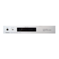
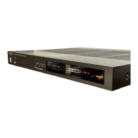
Arrangement of system components in a horizontal layout.

Vertical Component Stacking

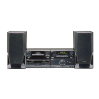
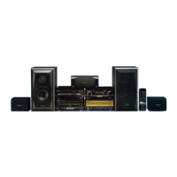
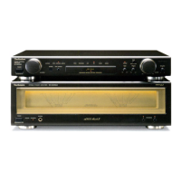
Arrangement of system components in a vertical layout.

Connections

Flat Cable Connection Guide

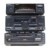
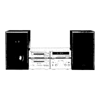
Connects tuner, CD player, and cassette deck using flat cables.

FM Indoor Antenna Connection

How to connect the FM indoor antenna for best reception.

AM Loop Antenna Connection

How to attach and connect the AM loop antenna.

Speaker Cable Connection

Proper connection of left and right speaker cables to terminals.

AC Power Supply Cord Connection

Connecting the AC power cord to the unit and outlet.

External Unit Connection - DCC/DAT

Connecting digital audio equipment like DCC or DAT decks.

External Unit Connection - Analog Player

Connecting an analog player via stereo connection.

Rear Surround Speakers Connection

Connecting the amplifier to rear surround speakers.

Location of Controls

Disassembly Instructions

Cabinet Removal Procedure

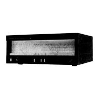
Steps to remove the external cabinet of the unit.

Front Panel Assembly Removal

Procedure to detach the front panel assembly.

FL P.C.B. Removal

Steps to remove the Flat Panel (FL) Printed Circuit Board.

Mic/Headphones Jack PCB Removal

Procedures for removing PCBS for mic and headphone jacks.

Power Button/Light Panel Removal

Steps to remove the power button and light panel components.

Disassembly Instructions (Continued - Rear Grill, AC IN, Fan, Transformer)

Rear Grill Assembly Removal

Steps to remove the rear grill assembly.

AC IN Terminal PCB Removal

Procedure to detach the AC input terminal PCB.

Fan Assembly Removal

Steps to remove the unit's fan assembly.

Power Transformer Removal

Procedure to detach the main power transformer.

Power Transformer PCB Removal

Steps to remove the power transformer's PCB.

Disassembly Instructions (Continued - Main PCB, ICs, Foot)

Main P.C.B. Removal

Procedure to remove the main printed circuit board.

Power IC/Regulator Transistor Removal

Steps for removing power IC and regulator transistors.

Main P.C.B. Checking

Guidance on inspecting the main PCB for issues.

Foot Replacement

Instructions for replacing the unit's feet.

Fan Motor Assembly Disassembly

Detailed steps for disassembling and removing the fan motor and case.

Power Source On/Off

Schematic Diagram: FL/Headphones/Mic Jack Circuits

FL Circuit Schematic

Schematic for the Front Panel (FL) display circuit.

Headphones Jack Circuit Schematic

Schematic for the headphones jack circuit.

Mic Jack Circuit Schematic

Schematic for the microphone jack circuit.

Schematic Diagram: Main/Power Transformer/AC Input Circuits

Main Circuit Schematic

Schematic diagram for the main circuit board.

Power Transformer Circuit Schematic

Schematic for the power transformer and related components.

AC Input Terminal Circuit Schematic

Schematic for the AC input terminal circuit.

Wiring Connection Diagram

Block Diagram

Function of IC Terminals

Replacement Parts List

Cabinet Parts Location

Accessories (Packaging Context)

Cabinet Parts Location (Continued)

Packaging

Related product manuals