EasyManua.ls Logo

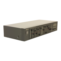
Technics SH-8028

Technics SH-8028
8 pages
To Next Page IconTo Next Page
To Previous Page IconTo Previous Page
Loading...
Mi
CONTENTS
Page
Page
SAFETY
PRECAUTION
....----+
200
e
ee
eaee
3
BLOCK
‘DIAGRAM
‘x
-6:0
4%
4-24
Si
Gi
k.
O09
we
Ae
oe
6
LOCATION
OF
CONTROLS..............4..
3,4
CIRCUIT
BOARDS
AND
WIRING
CONNECTION
DIAGRAM.
.7,8
OPERATION
bic
fous
be
SES
eee
ot
eee
ears
4
SCHEMATIC
DIAGRAM
...........002
eee
ener
eeae
9,
10
DISASSEMBLY
INSTRUCTIONS
..............-
5
REPLACEMENT
PARTS
LIST
...........0
cece
sees
11,12
RESISTORS
and
CAPACITORS
.............-4-
6
EXPLODED:
VIEW
ice
i.e
Se
i
ew
ard SLE
6
BR
a
11,12
a3
SAFETY
PRECAUTIONS
(This
“safety
precaution”
is
applied
only
in
U.S.A.)
Before
servicing,
unplug
the
power
cord
to
prevent
an
electric
shock.
When
replacing
parts,
use
only
manufacturer’s
recommended
components
for
safety.
Check
the
condition
of
the
power
cord.
Replace
if
wear
or
damage
is
evident.
After
servicing,
be
sure
to
restore
the
lead
dress,
insulation
barriers,
insulation
papers,
shields,
etc.
Before
returning
the
serviced
equipment
to
the
customer,
be
sure
to
make
the
following
insulation
resistance
test
to
prevent
the
customer
from
being
exposed
to
a
shock
hazard.
hg
ON
INSULATION
RESISTANCE
TEST
1.
Unplug
the
power
cord
and
short
the
two
prongs
of
the
plug
with
a
jumper
wire.
2.
Turn
on
the
power
switch.
3.
Measure
the
resistance
value
with
ohmmeter
between
the
jumpered
AC
plug
and
each
exposed
metal
cabinet
part,
such
as
screwheads
antenna,
control
shafts,
handle
brackets,
etc.
Equipment
with
antenna
terminals
should
read
between
3MQ2
and
5.2MQ2
to
all
exposed
parts.
(Fig.
A)
Equipment
without
antenna
terminals
should
read
approximately
infinity
to
all
exposed
parts.
(Fig.
B)
Note:
Some
exposed
parts
may
be
Isolated
from
the
chassis
by
design.
These
will
read
infinity.
Antenna
terminal
Exposed
Exposed
metal
metal
part
part
Onmmeter
Onhmmeter
(Fig.
A)
(Fig.
B)
Resistance
=
3M2—5.2MQ
Resistance
=
Approx
oo
4.
|f
the
measurement
is
outside
the
specified
limits,
there
is
a
possibility
of
a
shock
hazard.
The
equipment
should
be
repaired
and
rechecked
before
it
is
returned
to
the
customer.
Mi
LOCATION
OF
CONTROLS
16kHz
63Hz
6.3kHz
160Hz
cieet
ai
)
400Hz
|
Right
channel
controls
TkHz
1kHz
band
level
controls
(+12dB)
400Hz
2
5kHz
(+12dB)
160Hz
6.3kHz
One
16kHz
Equalizer
switch
(..-
on,
H
off)
Recording
mode
selector
Power
switch
(=
EQ,
@
straight)
(
=
on,
Hoff)
Input
selector
(
m
tape,
J
source)
{_
selector
For
[XA]
,[PA]
and[PE]
areas
AC
outlet
(Unswitched)
For
[M],{[MC]
,[XA]
,[PA]
and
[PE]
areas
Line
input
Line
output
Mi
OPERATION
ey
Input
selectors:
Select
the
sound
source.
Q
Loudness
switch:
‘‘off’’
@
‘‘AV/aux”:
To
use
equipment
connected
to
the
auxiliary
input
(““AV/AUX’’)
terminals.
@
Tape-monitor
selector:
‘‘tape
1/DA
tape”’
(Refer
to
note).
@
“CD”:
To
listen
to
a
compact
disc.
(The
“tape”
indicator
will
be
illuminated)
‘tuner’
—To
listen
to
radio
broadcasts.
“phono”:
To
listen
to
phono
discs.
6)
Balance
control:
‘‘center
position”
ye
CD
direct
switch:
‘‘off’’
©
Tone
controls:
“center
position”
To
listen
to
CD
direct:
“on”
©
Power
switch:
“‘on’-
fm
Volume
control:
“Q—1”
Integrated
amplifier
(option)
®
Begin
the
disc
play
or
tune
to
the
radio
broadcast.
ry)
Adjust
volume
level.
fe)
‘‘on”’
(H_
m)
iE)
Adjust
tone
quality
as
desired.
This
unit
(SH-8028)
12
i
oe
[oyster
Press
the
equalization
switch
(equalizer)
in
to
the
‘‘off’’
(=.
H)
position
to
listen
to
uncorrected
sound,
or
when
recording.
“tape”
(H_.
=)
Set
to
any
position.
Notes
e
Ifthe
amplifier
has
a
recording
mode
selector
and
an
input
selector:
(Make
setting
as
shown
in
the
figure.)
Lanne
eal
|
//
NY
input
select
SJ
or
tuner
U
|
a0
Ro)
a
or)
oO
OO
ODO
000
0
O
e
If
your
amplifier
has
terminals
(GRAPHIC
EQ./EXTERNAL)
for
connection
of
other
equipment,
use
of
the
recording
selector
is
unnecessary.
on
Mi
DISA
Ref.
No.
1
Procedure
1
Ref.
No.
2
Procedurt
1-2
@
Rer
Ref.
No.
3
Procedure
1-2—

Related product manuals