EasyManua.ls Logo

Technics SH-E5

Technics SH-E5
13 pages
To Next Page IconTo Next Page
Loading...
ORDER
NO.
SD82062214c8
Service
Manual
Stereo
Graphic
Equalizer
OH-E5
[D],[EK],[EW],[EB],
[EF],[EGA],[EH],
[XA]
XL
]
SH-ES
(W)
]
[D],[EK],[
EW],
[EB],
[EF],[EGA],[EH],
[XA],[XL
*
[D]
is
available
in
Scandinavia.
*
[EK]
is
available
in
United
Kingdom.
*
[EW]
is
available
in
Switzerland.
*
[EB]
is
available
in
Belgium.
*
[EF]
is
available
in
France.
*
[EGA]
is
available
in
F.R.
Germany.
*
[EH]
is
available
in
Holland,
*
[XA]
is
available
in
Southeast
Asia,
Oceania,
Africa,
Middle
Near
East
and
Central
South
America.
*
[XL]
is
available
in
Australia.
*
The
cabinet
and
front
panel
are
available
in
black
color
and
silver
types.
*
The
black
type
model
is
provided
with
(K)
in
the
Service
Manual.
Specifications
(Specifications
are
subject
to
change
without
notice
for
further
improvement.)
(DIN
45
500)
Band
level
controls
:+12dB~-12dB
Frequency
response
(center
position)
:5
Hz~100
kHz,
—1
dB
(12
elements
continuously
variable
per
channel)
Maximum
output
Center
frequency
216
Hz,
31.5
Hz,
63
Hz,
125
Hz,
voltage
:
8V(1
kHz,
THD
0.01%)
250
Hz,
500
Hz,
1
kHz,
2
kHz,
Rated
output
voltage
:1V
4
kHz,
8
kHz,
16
kHz,
32
kHz
Rated
total
harmonic
distortion
:
0.005%
(20
Hz~20
kHz)
GENERAL
0.003%
(1
kHz)
Power
supply
:
AC
240
V
50
Hz
only
(For
Australia
Input
sensitivity
“1V
and
for
United
Kingdom)
Signal-to-noise
ratio:
100
dB
(110
dB,
IHF’
A)
AC
220
V
50
Hz
only
(For
Germany
Maximum
input
and
for
Switzerland)
voltage
:8V
(1
kHz)
AC
110
V/120
V/220
V/240
V,
Input
impedance
247kO
50
Hz/60
Hz.
(For
areas)
Gain
:0+1dB
Power
consumption
:17W
Channel
balance
Dimensions
250
Hz~6300
Hz
:+0.5dB
(HxWxD)
>50x315x240
mm
Channel
separation
(2’’X
12-13/32’’x
9-7/16"’)
1kHz
:60
dB
Weight
12.0
kg
(4.4
Ib)
B
CONTENTS
Page
Page
LOCATION
OF
CONTROLS
....................
2
SCHEMATIC
DIAGRAM...................0004
9
TOTAL
FREQUENCY
RESPONSE
................
3
EXPEODEDEVIEWE
tes
ee
os
a
a
ws
Go
ev
13
DISASSEMBLY
INSTRUCTIONS
.................
3
REPLACEMENT
PARTS
LIST
................00.4
15
BLOCK
DIAGRAM#ieclar..
<
.
cosecta
seesiecs
eee
ta
5
RESISTORS
&
CAPACITORS
...................
16
CIRCUIT
BOARDS
AND
WIRING
CONNECTION
DIAGRAM................000.
6
Matsushita
Electric
Trading
Co..
Ltd.
P.O.
Box
228,
Central
Osaka
Japan
‘Technics
Question and Answer IconNeed help?

Do you have a question about the Technics SH-E5 and is the answer not in the manual?

Technics SH-E5 Specifications

General IconGeneral
BrandTechnics
ModelSH-E5
CategoryRecording Equipment
LanguageEnglish

Summary

Technical Specifications

Frequency Response

Specifies the frequency range and tolerance of the audio signal.

Maximum Output Voltage

Defines the highest voltage output the unit can produce.

Rated Output Voltage

The standard voltage output under normal operating conditions.

Rated Total Harmonic Distortion

Measures the level of unwanted harmonic frequencies in the output.

Input Sensitivity

The minimum input signal level required for a specified output.

Signal-to-Noise Ratio

Ratio of the desired signal power to the noise power.

Maximum Input Voltage

The highest input voltage the unit can safely handle.

Input Impedance

The electrical resistance presented by the input terminals.

Gain

The amplification factor of the signal.

Channel Balance

Measures the difference in output level between left and right channels.

Channel Separation

Measures how well the left channel is isolated from the right channel.

Band Level Controls

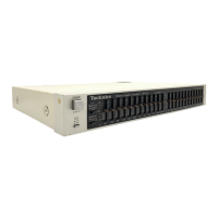
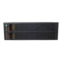
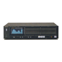
Controls for adjusting the level of specific frequency bands.

Center Frequency

Defines the central frequencies for each band equalizer.

General Power Supply

Information regarding the unit's power source requirements.

Power Consumption

The electrical power consumed by the unit during operation.

Dimensions

Physical size of the unit (Height, Width, Depth).

Weight

The mass of the unit.

Location of Controls

Disassembly Instructions

How to Remove the Front Panel

Step-by-step guide for detaching the front panel assembly.

How to Remove the PCB

Procedure for safely removing the printed circuit board.

How to Remove the Slide Volume

Instructions for disassembling the slide volume controls.

How to Set the Film

Guide on correctly positioning the film for volume levers.

How to Remove the Direct Connector

Steps for detaching the direct connector assembly.

Block Diagram

Circuit Boards and Wiring Connection Diagram

Schematic Diagram

Exploded Views

Replacement Parts List

Resistors & Capacitors

Related product manuals