Do you have a question about the Technics SH-8028 and is the answer not in the manual?
Procedure to test insulation resistance for shock hazard prevention.
Step-by-step guide for basic operation and adjustments.
Important considerations for amplifier connection and usage.
Steps to safely detach the main cabinet from the unit.
Procedure for removing the front panel assembly.
Instructions for removing power and switch circuit boards.
Steps to detach the band level control volume circuit board.
Guide on correctly installing the volume control rod.
Explanation of the numbering conventions for resistors.
Explanation of the numbering conventions for capacitors.
List of specific resistors with their part numbers and values.
List of specific capacitors with their part numbers and values.
Diagram for the input/output jack and switching circuit.
Circuit board diagram for the volume control section (left channel).
Circuit board diagram for the power supply section.
Circuit board diagram for the volume control section (right channel).
Schematic of the input/output jack and switching circuit.
Schematic of the muting circuit.
Schematic of the power supply circuit.
Schematic of the volume control and equalization circuitry.
Diagrams for voltage selector and AC outlet configurations.
List of integrated circuits with part numbers.
List of transistors with part numbers.
List of diodes with part numbers.
List of transformers with part numbers.
List of variable resistors with part numbers.
List of switches with part numbers.
| Brand | Technics |
|---|---|
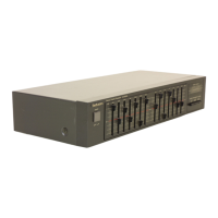
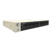
| Model | SH-8028 |
| Category | Recording Equipment |
| Language | English |