EasyManua.ls Logo

Technics SH-CH900

Technics SH-CH900
23 pages
To Next Page IconTo Next Page
Loading...
ORDER
NO. AD9111262C2
Service
Manual
Sound
Processor
SB-CH900
c
DOLBY SURROUIMD
PRO
LOGIC
SB-CH900-
Remote
Control Transmitter
Because
of unique interconnecting
cables,
when a component requires
service,
send or
bring in the entire
system.
SPECIFICATIONS
PRE AMP. SECTION
Input
sensltivity and impedance
PHONO 2.5 mV/47 kQ
VCR/VDP
(Input
with
PHONO PIN) 250 mV/18 kQ
Total harmonie distortion
1
kHz,-3 dB
output
0.08%
DOLBY
PRO-LOGIC,
EQUALIZER,
SOUND
FIELD
PROCESSOR
SECTION
Dolby surround
Mode
Delay
time
Tone
control
Bass
Treble
Equalizer
Center
frequency
LOW
HIGH1,2
NORMAL,
WIDE,
PHANTOM,
3
STEREO
15-30
m
sec.
±10dB
±10dB
31.5,
40, 50, 63,
80,100,125,180,
220 (Hz)
315,450,630,
800,
1
k, 1.25 k, 1.6 k, 2.2 k, 3.15 k,
4.5
k, 6.3 k, 8 k, 10 k, 12.5 k, 16 k (Hz)
Level
control LOW, HIGH1, 2 ±12 dB
(Q) control Narrow 1.8
Wide
-msv
Fixed
mode
Equalizer
(6 modes)
HEAVY,
CLEAR,
SOFT,
VOCAL
HEADPHONE
STEREO,
CAR
STEREO
riaaioeii i eievisieservice
„KEES
van de MORTEL"
Boksheuvelstraat
14
5222
AN
's-HERTOGENBOSCH
Tel.:
073 - 218344
A
Sound
Processor
SH-CH900
Color
(K)
Black
Type
rea
ai ar
Country
Code
Area
Color
Continental Europa.
Great
Britain.
Germany
and Italy.
(E)
Asia,
Latin America,
(K)
Middle
Near
East
and
Africa.
Oceania.
System:
SC-CH900
Sound
Field
Processor
(6 modes)
HALL,
LIVE,
DISCO,
CHURCH
STADIUM,
THEATER
Frequency
response
PHONO
TUNER,
TAPE,
VCR
CD,
DAT, VDP
S/N
PHONO
TUNER,
TAPE,
VCR
CD,
DAT, VDP
Key
control
MIc echo
Video
output
MONITOR
VCR
REC
OUT
ottud loitnoo-
GENERAL
Dlmenslons(WxHxD) H'"
Welght
RIAA
STANDARD
CURVE
(30
Hz-15 kHz)+1.0,-1.5 dB
15HZ-20
kHz,-1 dB
15HZ-20
kHz,-1 dB
64
dB (DIN)
85
dB
(IHF,
at
full
scale
input,
IHF A)
71
dB (DIN)
90
dB
(IHF,
at
full
scale
input,
IHF A)
93
dB
-300-+300 cent
0.2-1.6 sec
1 Vpp/75n
1 Vpp/75n
230x83x292
mm
1.95 kg
Notes:
1.
Specitications are subject to change
without
notlce.zyxwvutsrqponmlkjihgfedcbaZYXWVUTSRQPONMLKJIHGFEDCBA isU
(C
t)
2.
Weight and dimensions shown are approximate.
3.
Total harmonie
distortion
is measured by the
digital
spectrum
analyzer.
System
Tuner/CD
player
Sound
Processor
Amplifier
Cassette
Deck
Speal<ers
SC-CH900
SL-CH900
SH-CH900
SU-CH900
RS-CH900
'SB-CH900
Teclmics
•(E)
area...lVladelnPAES
Question and Answer IconNeed help?

Do you have a question about the Technics SH-CH900 and is the answer not in the manual?

Technics SH-CH900 Specifications

General IconGeneral
Channels2
Total Harmonic Distortion0.005%
TypeGraphic Equalizer
InputsLine
OutputsLine, Headphones
Heads2x playback, 2x recording, 2x erase
MotorDC servo motor
Frequency Response (Cassette Deck)30Hz to 16kHz (Metal Tape)
Signal-to-Noise Ratio (Cassette Deck)56dB (Dolby NR off), 66dB (Dolby B), 78dB (Dolby C)
Wow and Flutter0.18% WRMS
Dimensions (Cassette Deck)360 x 119 x 290 mm
Weight (Cassette Deck)4.2 kg

Summary

System Specifications

Pre-Amplifier Section Specifications

Details input sensitivity, impedance, and harmonic distortion for the pre-amplifier.

Sound Processor and Field Processor Specifications

Covers Dolby Pro-Logic, equalizer, sound field modes, delay time, and tone control.

General Unit Specifications

Includes physical dimensions, weight, and power requirements for the sound processor system.

System Controls and Operation

System Control Locations and Functions

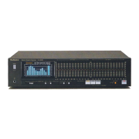
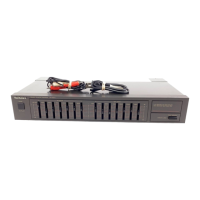
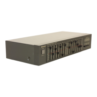
Identifies and explains the function of each front panel control button and indicator.

Technical Diagrams and Schematics

Disassembly Procedures

Step-by-step guide for safely disassembling the sound processor unit for servicing.

System Block Diagram

Illustrates the overall signal flow and functional blocks within the sound processor.

Schematic Diagrams

Detailed circuit diagrams for main, input-output, Dolby, and FL/operation circuits.

Printed Circuit Board Layouts

Visual layout of main, FL, operation, input-output, and Dolby PCBs with component placements.

Component Information and Wiring

Wiring Connection Diagram

Shows interconnection between the main PCB, operation PCB, FL PCB, and input-output PCB.

FL Panel Display Description

Details grid assignment, pin connections, and anode connections for the front panel display.

Integrated Circuit Terminal Functions

Lists the function of each pin for key integrated circuits within the system.

Replacement Parts List

Comprehensive list of replacement parts: ICs, transistors, diodes, resistors, capacitors, connectors.

Cabinet Parts Location

Illustrates location and part numbers for cabinet components and assembly parts.

Related product manuals