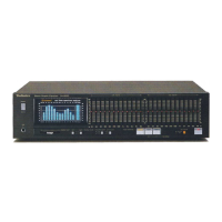
SH-CH900
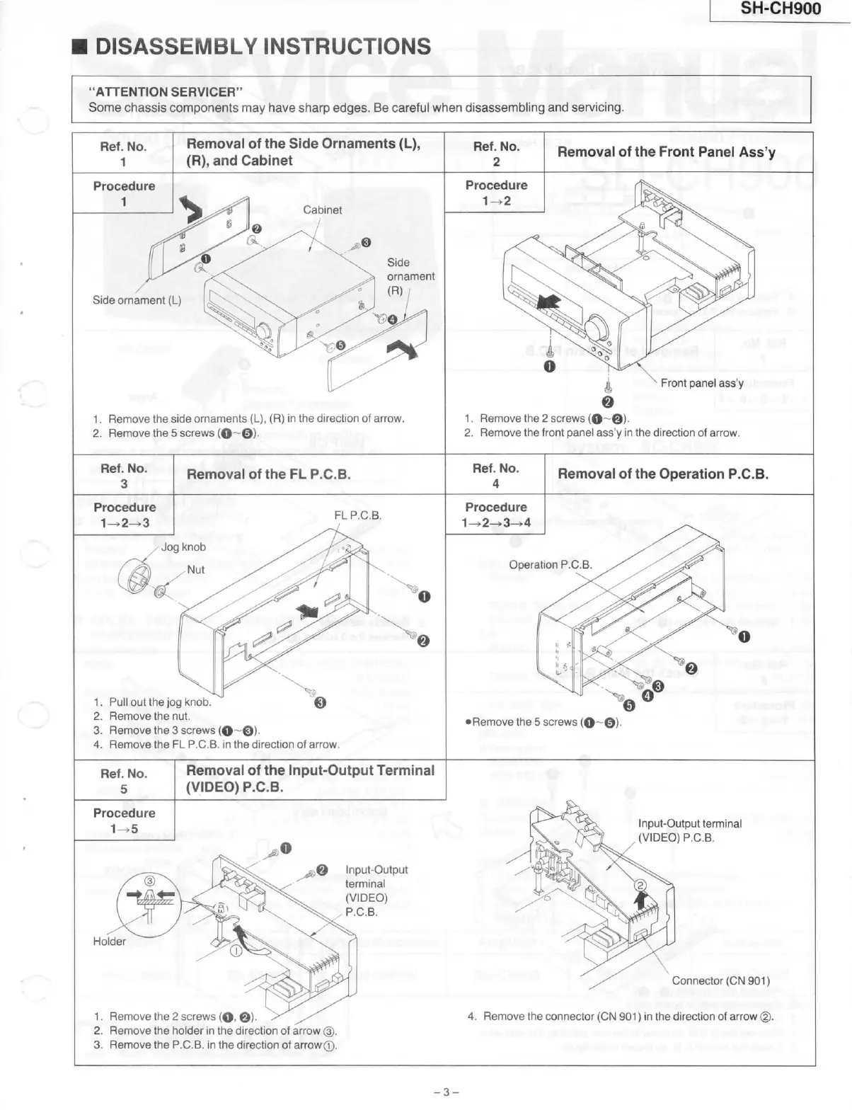
DISASSEMBLY
INSTRUCTIONS
"ATTENTION
SERVICER"
Some
chassis
components may have sharp edges. Be careful when disassembling and servicing.
Ref. No.
1
Removal of the Side Ornaments (L),
(R),
and Cabinet
Ref. No.
2
Removal of the Front Panel
Ass'y
Procedure
1
Cabinet
/
Procedure
1
Side
ornament (L)
Side
ornament
(R)
••..-'i-iA
1.
Remove the side ornaments
(L),
(R) in the
direction
of arrow.
2.
Remove the 5 screws (0~©)
•
Front panel
ass'y
1.
Remove the 2 screws (O~0)-
2.
Remove the
front
panel
ass'y
in the
direction
of arrow.
Ref. No.
3
Removal of the FL
P.C.B.
Ref. No.
4
Removal of the Operation
P.C.B.
FL
P.C.B.
Procedure
Operation
P.C.B.
1.
Pull out the jog knob.
2.
Remove the nut.
3.
Remove the 3 screws
(0~©)-
4.
Remove the FL
P.C.B.
in the
direction
of arrow.
•Remove the 5 screws
{0~©)-
Ref. No.
5
Procedure
1-^5
Removal of the
Input-Output
Terminal
(VIDEO)
P.C.B.
O
Input-Output
terminal
(VIDEO)
,
P.C.B.
Holder
1.
Remove the 2 screws (O. ©)
2.
Remove the
holder
in the
direction
of arrow (
3.
Remove the
P.C.B.
in the
direction
of arrow®.
Input-Output
terminal
(VIDEO)
P.C.B.
Connector (CN 901)
4.
Remove the connector (CN 901) in the
direction
of arrow
(2).
-3-