EasyManua.ls Logo

Technics SH-8065

Technics SH-8065
17 pages
To Next Page IconTo Next Page
Loading...
*
The
cabinet,
front
panel
and
knob
are
available
in
black
color
and
silver
types.
*The
black
type
model
is
provided
with
(K)
in
the
Service
Manual.
Specifications
(DIN
45
500)
Frequency
response
(center
position):
Maximum
output
voltage:
Rated
output
voltage:
Rated
total
harmonic
distortion:
input
sensitivity:
Signal-to-noise
ratio:
Maximum
input
voltage:
Input
impedance:
Output
impedance:
Gain:
Band
level
controls:
Signal
level
selector:
Service
Manual
ORDER
NO.
$D82032136C8
Stereo
Graphic
Equalizer
Areas
SH-
8065
SH:
8065
c
*
[EX]
is
available
in
Switzerland
and
Scandinavia.
*
[EK]
is
available
in
United
Kingdom.
*
[EF]
is
available
in
France.
*
[XA]
is
available
in
Southeast
Asia,
Oceania,
Africa,
Middle
Near
East
and
Central
South
America.
Specifications
are
subject
to
change
without
notice
for
further
improvement.
Weights
and
dimensions
shown
are
approximate.
5
Hz~100
kHz,
-1dB
8
V
(1
kHz,
THD
0.01%)
1V
0.0025%
(20
Hz~20
kHz)
1V
100
dB
(110
dB,
IHF’
A)
8
V
(1
kHz)
47kQ
6000
0+1dB
+12dB~-12dB,
+3dB~-3dB
(33
elements
continuously
variable
per
channel)
150
mV/1V
Center
frequency:
GENERAL
Power
supply:
Power
consumption:
Dimensions
(HxWxD):
Weight:
16
Hz,
20
Hz,
25
Hz,
31.5
Hz,
40
Hz,
50
Hz,
63
Hz,
80
Hz,
100
Hz,
125
Hz,
160
Hz,
200
Hz,
250
Hz,
315
Hz,
400
Hz,
500
Hz,
630
Hz,
800
Hz,
1
kHz,
1.25
kHz,
1.6
kHz,
2
kHz,
2.5
kHz,
3.15
kHz,
4kHz,
5
kHz,
6.3
kHz,
8
kHz,
10
kHz,
12.5
kHz,
16
kHz,
20
kHz,
25
kHz
AC
110
V/120
V/220
V/240
V,
50
Hz/60
Hz
29W
153x430
x
330
mm
(6-1/32”’
x
16-15/16’’
x
13"’)
6.6
kg
(14.6
Ibs)
m@
CONTENTS
Page
Page
LOCATION
OF
CONTROLS.........-
00
eee
eee
eet
2
BLOCK
DIAGRAM.
.......
2.020
eee
wee
ee
ee
ee
13
TOTAL
FREQUENCY
RESPONSE
..........-.2.--.0085
3
SCHEMATIC
DIAGRAM
....
2...
2
eee
ee
ee
ee
es
14
DISASSEMBLY
INSTRUCTIONS
...........0022
0008
4
EXPLODED
VIEW...
1...
ee
ee
ee
ee
ns
19
REPLACEMENT
PARTS
LIST
REPLACEMENT
PARTS
LIST
Resistors,
Capacitors
and
Electrical
Parts
...........-.
5
Cabinet,
Chassis
and
Packing
Parts
.......-.0-2e005
20
PRINTED
CIRCUIT
BOARDS..........-.-+220008
0%
7
Matsushita
Electric
Trading
Co.,
Ltd.
P.O.
Box
288,
Central
Osaka
Japan
Technics
Question and Answer IconNeed help?

Do you have a question about the Technics SH-8065 and is the answer not in the manual?

Technics SH-8065 Specifications

General IconGeneral
Frequency Range20 Hz - 20 kHz
Number of Bands10
Weight3.5 kg
Control Range±12 dB
TypeEqualizer
Output Impedance600 Ohms
Power SupplyAC 120V
Dimensions430 x 70 x 250 mm
Gain0dB
Input Sensitivity1V
Frequency Bands100Hz, 250Hz, 400Hz, 630Hz, 1kHz, 2.5kHz, 4kHz, 6.3kHz, 10kHz, 16kHz

Summary

Product Specifications Overview

Equalizer Center Frequencies

Lists all center frequencies for the equalizer bands.

General Unit Specifications

Covers power supply, consumption, dimensions, and weight.

Controls and Indicators Guide

Front Panel Controls and Switches

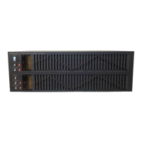
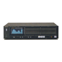
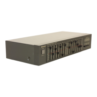
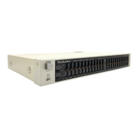
Details switches, selectors, and band-level controls on the front panel.

Rear Panel Connectivity

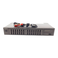
Describes rear panel input/output jacks and voltage selector.

Frequency Response Characteristics

Frequency Response Graph

Visual representation of the unit's frequency response across various settings.

Internal Circuitry Overview

Highlights key internal circuits like power supply and band-level control.

Unit Disassembly Procedures

Front Panel Removal Guide

Step-by-step guide to safely detach the front panel.

Bottom Board Removal Instructions

Instructions for removing the bottom chassis panel.

Slide Volume and Knob Detachment

Procedures for removing slide volume controls and attaching knobs.

Component Replacement Parts List

Resistors and Capacitors Listing

Detailed listing of resistors and capacitors with part numbers and values.

Electrical Component Details

List of Electrical Components

Lists integrated circuits, transistors, diodes, relays, switches, coils, and fuses.

Printed Circuit Board Layouts

33 Band Level Control PCB Diagram

Diagram showing the layout for the 33 band level control PCB.

Component Terminal Guides

Pinout guides for transistors, ICs, and diodes.

System Block Diagram

Signal Flow and Functional Blocks

Overview of signal paths and functional blocks within the equalizer.

Schematic Diagram - Section A

Power Supply and Control Circuits

Details power supply, equalizer selector, and buffer/operation amplifier circuits.

Band Level Control Circuit

Schematic for the band level control section.

Schematic Diagram - Section B

Band Pass Filter Circuits

Detailed schematic of the band pass filter circuits for each frequency band.

Exploded View and Parts

Cabinet, Chassis, and Packing Parts

Lists cabinet, chassis parts, screws, washers, and packing materials.

Service Manual Revisions

Resistor Part Number Updates

Details changes in part numbers for specific resistors.

Circuit Modification Details

Information on circuit changes, particularly for the input terminal circuit.

Related product manuals