Do you have a question about the Technics SH-GE90 and is the answer not in the manual?
Details frequency response, output voltage, distortion, sensitivity, and impedance.
Details key control and microphone echo settings.
Lists power consumption, power supply, dimensions, and weight.
Lists stereo connection cable part numbers.
Lists AC power supply cord part numbers for different areas.
Lists power plug adaptor part number for GC area.
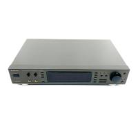
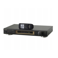
Explains front panel controls like Power, Mic Volume, Key Control, Echo, Display, Memory.
Describes Multi-level display, Echo indicator, SFP indicator, Key control indicator, Voice mute indicator.
Guides on connecting stereo cables to the unit and amplifier.
Instructions for setting the voltage selector for different regions.
Details on connecting the power cord and insertion of connectors.
Step-by-step guide to remove the main cabinet.
Instructions for removing the front panel assembly.
Steps to remove the Front Light Printed Circuit Board.
Guide to remove power switch/volume and MIC jack PCBs.
Steps to remove the Operation Printed Circuit Board.
Steps to remove the Karaoke Printed Circuit Board.
Steps to remove the Main Printed Circuit Board.
Steps to remove the Power Supply Printed Circuit Board.
Procedure to check and reassemble PCBs for power, mic jack, and operation.
Instructions for checking the Main Printed Circuit Board and reassembly.
Guide on how to replace the unit's feet.
Front Light circuit schematic.
Karaoke circuit schematic.
Operation circuit schematic.
Main circuit schematic.
Microphone Jack circuit schematic.
Power supply circuit schematics for different areas.
Printed circuit board layout for the Front Light.
Printed circuit board layout for the Karaoke section.
Printed circuit board layout for the Operation section.
Printed circuit board layout for the Main unit.
Printed circuit board layout for the MIC Jack.
Printed circuit board layout for Power Switch/Volume.
Printed circuit board layouts for Power Supply for different areas.
Visual representation of internal wiring connections between PCBs.
Details FL panel grid assignment and pin connections.
Details terminals and functions for IC303.
Details terminals and functions for IC501.
Details terminals and functions for IC801.
Details terminals and functions for IC802.
Block diagram of input and mode selection circuitry.
Block diagram of digital delay and DSP processing sections.
Block diagram of A/D converter and digital filter sections.
Block diagram of system control and FL display drive circuits.
List of integrated circuits with part numbers and descriptions.
List of transistors with part numbers and descriptions.
List of diodes with part numbers and descriptions.
List of switches with part numbers and descriptions.
List of connectors with part numbers and descriptions.
List of coils with part numbers and descriptions.
Diagram showing the location of various cabinet parts.
Information on packaging materials and included accessories.
| Brand | Technics |
|---|---|
| Model | SH-GE90 |
| Category | Computer Hardware |
| Language | English |