m@
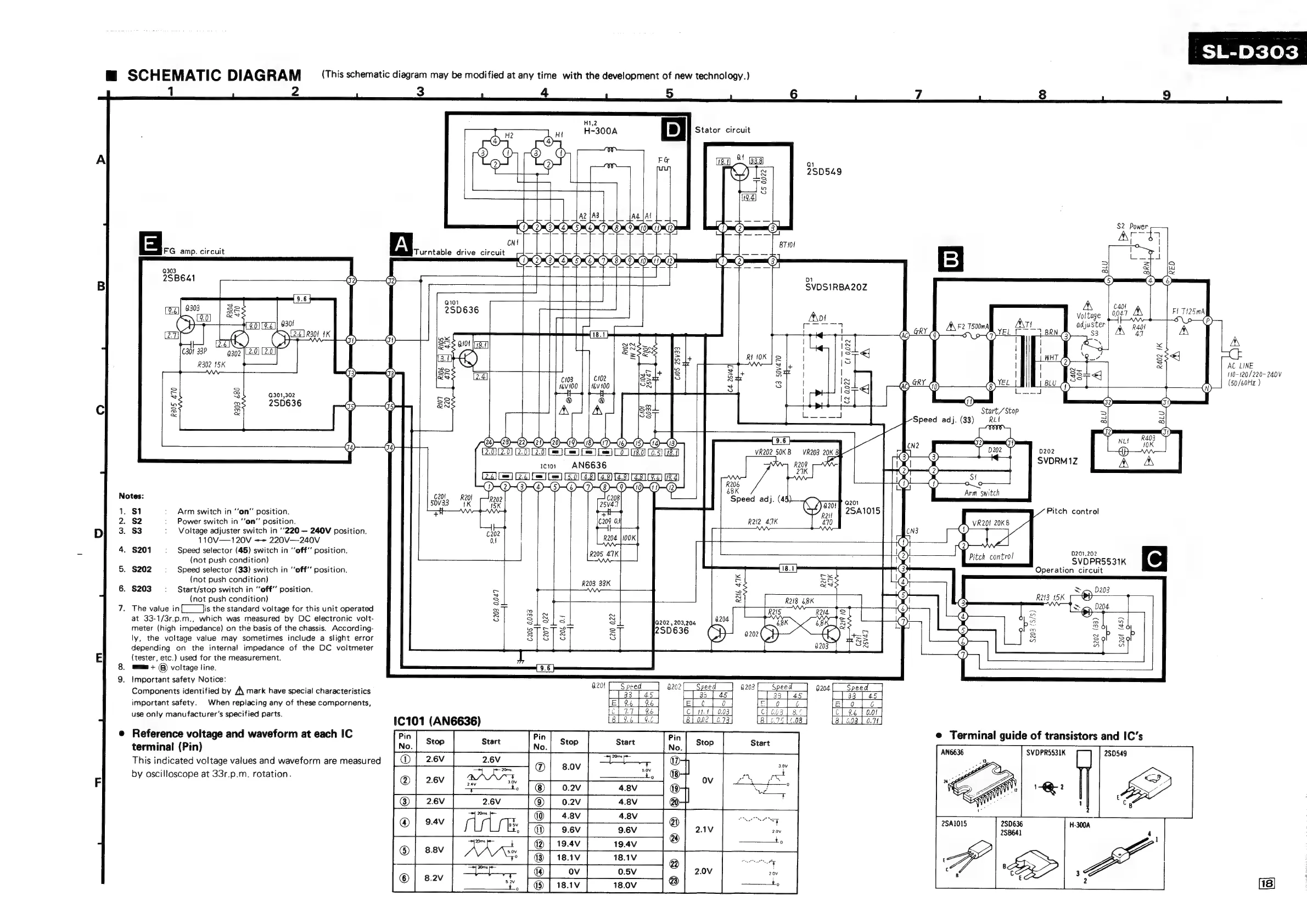
SCHEMATIC
DIAGRAM
(This
schematic
diagram
may
be
modified
at
any
time with
the
development
of
new
technology.)
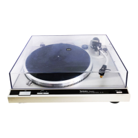
SL-D303
1
2
3
4
5 6
7
8
9
H1,2
ap
7)
MI
H-300A
Stator
circuit
4
4
3
{
3
{
A
2
2
ae.
el
Gea
a
Sy
2SD549
i=}
—)
&
19.4]
os
ie
AZ{A3
|
|
[Ad
SAL
Net
tl
od
22
D@,0,06,06,6,0,0,0,0,0,0
me
{mat
2
3
S2
Power
an
m
mt
x
Jat
re
45)
Se
os
cnt
BT10/
|
|
FG
amp.
circuit
Turntable
drive
circuit
—
sl
_
—
a
t
4d
10,0,6,C,6,6,0,0,0,0,0,0,
DO
3
2
“zt
ola
9303
=
=
SS
z
&
wi
2SB641
o2
)
D1
5
DG
B
SVDSIRBA20Z
[g]|
2303
Ss
5
250636
10
og)
|
&8
Apt
voltage
[0047
FI
cou
(9.0)
[9.6])
930!
feet
A\
F2
T500mA
At
Tt
adjuster
aol
A
(27
[2.2]
R30!
1K
18.1
!
Ag-—8X(G
DELL
BRN
3
41
Cy)
ox
|
~
|
|
~,
A
cara
zo
ca
aug
ON
as
BXsaes
fp
iS
mle
i
«
5
‘
SN
hae
302
|l2-0)
2.0]
Ser
ede
RIK
fe]
|
7S
|
WHT
®
Se_
xs€j
R302
15K
ae
z
2
S
3
fy
|
i
|
|
oe
&
AC
LINE
c=}
S
Ss
eS
a
3
03
ss
[ad]
Fibs
nie
seit
IS
sat
5
|
ie
ae
om
|
|
;
337€
i
Tie
240V
~
=~
16V100
|
|
14v
100
Sok
+
3
I
i3
<j
0)
10
3
LU
:
50/60Hz
S
3
al
ae
#
#
=
a
A
Ld
Lo
2
SD636
Ss
ie
2
)
af
Cc
Ss
S
:
,
a
A
IIA
88
e
:
Start,
/Stop
&
=
=
FES
Speed
adj.
(33)
RL
a
a
G2
-
}
,
i
0)
—(23)—22)
2-20)
1
1)
IDI
ID—03
9.6
CN?
2
a)
nu
Aa
(2.0)
(2.0)
C=)
Come]
fem]
foe
Lo)
8.0)
(0.5)
08.
VR202
50KB
—-VR203
20K
8
3
3
D202
D202
cio
+
~=AN6636
R209
i
:
|
x
SVDRM
1Z
A
A
Se
EE
a
oe
a
eee
|
St
DO
-O-O-O-D“
“2
ee
ne
i
is
Notes:
201
:
50v33
wy
Reo?
meee
Speed
adj.
(4
a201
4
2201
4
1.
$1
Arm
switch
in
‘‘on"'
position.
¥
7
Roll
2SA1015
Pitch
control
2.
S2
Power
switch
in
‘‘on”
position.
C209
Of
R22
4.7K
470
VR201
20KB
D
3.
$3
Voltage
adjuster
switch
in
‘’220
—
240V
position.
202
CN3
110V—120V
==
220V—240V
ot
alias
va
,
4.
$201
Speed
selector
(45)
switch
in
“off’’
position.
|
R205
47K
.
0201,202
(not
push
condition)
IS
Pieak
conte
SvOPRSS3ik
OF
5.
$202
Speed
selector
(33)
switch
in
“off”
position.
=
18.1
ae
3
Operation
circuit
(not
push
condition)
x
cx
R203
33K
a
4
6.
$203
Start/stop
switch
in
“off”
position.
a
=
aaa
x
Sey
D203
(not
push
condition)
$
2
R218
8K
1
3
R213
15K
7.
The
value
in{____
lis
the
standard
voltage
for
this
unit
operated
x
ol.
R26
Di
tS
é
ay,
Dg
1204
at
33-1/3r.p.m.,
which
was
measured
by
DC
electronic
volt-
Ss
SlS1s
8
6362205508
4204
NK
RTS
7
4
bo
>
>
meter
(high
impedance)
on
the
basis
of
the
chassis.
According-
eTorT
eT
=
2SD636
ss
:
:
Se
Lb
5
0
2
b
=
b
ly,
the
voltage
value
may
sometimes
include
a
slight
error
S/S]
Ss
$8
geo
7aS
Z
S
8
s
depending
on
the
internal
impedance
of
the
DC
voltmeter
8203
oS
”
a
E
(tester,
etc.)
used
for
the
measurement.
Ww
8,
am
+
©)
voltage
line.
9.6
9.
Important
safety
Notice:
Components
identified
by
A\
mark
have
special
characteristics
important
safety.
When
replacing
any
of
these
compornents,
use
only
manufacturer's
specified
parts.
j
[
[35
|
45
|
lel
¢
|
a
|
tt.4
|
0.03
1C101
(AN6636)
e
Reference
voltage
and
waveform
at
each
IC
terminal
(Pin)
by
oscilloscope
at
33r.p.m.
rotation.
|