EasyManua.ls Logo

Technics SL-DL1 Service Manual

Technics SL-DL1
28 pages
To Next Page IconTo Next Page
Page #1 background imageLoading...
Page #1 background image
ORDER
NO.
§D81051897C4
Service
Manual
Direct
Drive
Automatic
Turntable
System
=
OL-
DLI
*
[PA]
is
available
in
far
East
PX.
*
[PE]
is
available
in
European
Military.
[PA],
[PE],
[
*
[PC]
is
available
in
European
Audio
Club.
SL-DL1(
K)
*The
colors
of
this
model
included
silver
and
black.
*
The
black
type
model
is
provided
with
(K)
in
the
[PC]
Service
Manual.
For
additional
information,
please
refer
to
the
service
manual
for
Model
No.
SL-DL1/SL-DL1
(K)
(ORDER
NO.
$D81041862C8).
Notes:
*
This
service
manual
included
only
the
change
of
the
SL-DL1/SL-DL1
(K)
service
manual
(ORDER
NO.
SD81041862C8).
*
When
servicing
model
SL-DL1
[PA,
PE,
PC]
/SL-DL1
(K)
[PC],
this
service
manual
and
SL-DL1/SL-DL1
(K)
(ORDER
NO.
SD81041862C8)
service
manual
should
be
used
together.
@
REPLACEMENT
PARTS
LIST
Change
of
Part
No.
Per
Set
Remarks
SL-DL1/SL-DL1
(K)
ae
(kK)
|
Part
Name
&
Description
|
(p¢¢
)
)
(ORDER
NO.
SD81041862C8
(PA,
PE,
PC]
MAIN
CABINET
PARTS
SFNND11S01
SFNND11P01
SFNND11G02
SFNND11R01
SFNND11X01
SJA88
@FC1205M
AC
Cord
QFC1208M
SFUM190—11
SFUM190—12
ACCESSORIES
[PA]
,
[PE]}
Name
Plate
SFNND11P02
[PC]|
Name
Plate
4.
SFUM190—12
Bushing,
AC
Cord
SFNUD11S01
SFNUD11G01
SFNUD11P01
Instructions
Book,
Printed
Matter
SFNUD11X01
SFDK119118
Deletion
2
Pin
Plug
Addtion
QJPO603S
Adaptor,
Gimens
Panasonic
Tokyo
'
i
e2
nni
Matsushita
Electric
Industrial
Co.,
Ltd.
Matsushita
Electric
Trading
Co.,
Ltd.
Cc
1CS
1-2,
1-chome,
Shiba-koen,
Minato-ku,
Tokyo
105
Japan
P.O.
Box
288,
Centra
Ogsaka
Japan

Other manuals for Technics SL-DL1

Question and Answer IconNeed help?

Do you have a question about the Technics SL-DL1 and is the answer not in the manual?

Technics SL-DL1 Specifications

General IconGeneral
Drive SystemDirect Drive
Wow and Flutter0.025% WRMS
Signal to Noise Ratio78 dB
Tracking Force1.25g (fixed)
Power SupplyAC 120V, 60Hz
Weight5.5 kg
Turntable PlatterAluminum diecast
Speeds33 1/3, 45 rpm
Tonearm TypeLinear tracking
CartridgeMoving Magnet
Output Voltage2.5mV
Frequency Response20 Hz - 20 kHz
Rumble-78 dB (DIN B)

Summary

REPLACEMENT PARTS LIST

Main Cabinet Parts

Lists replacement parts for the main cabinet section of the turntable.

Accessories

Lists replacement parts for accessories included with the turntable.

Packing Parts

Lists replacement parts related to the packaging of the turntable.

Capacitors

Lists replacement capacitor components for the turntable.

Specifications

General Specifications

Provides general technical specifications for the SL-DL1 turntable.

Turntable Section Specifications

Details specifications related to the turntable platter and drive system.

Tonearm Section Specifications

Outlines specifications for the tonearm and its components.

Cartridge Section Specifications

Details specifications for the cartridge and stylus.

LOCATION OF CONTROLS

Top Panel and Front Controls

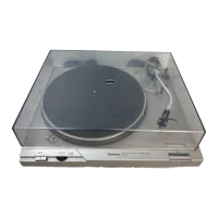
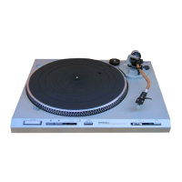
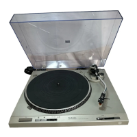
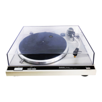
Identifies operational controls on the top and front panels of the turntable.

Tonearm, Platter, and Indicator Components

Details locations of tonearm, cartridge, platter, and visual indicators.

FEATURES

Dynamic Tracking Tonearm System

Highlights the linear tracking tonearm with optical sensor for stable tracking.

Operation Modes

Describes both simple automatic play and advanced complex functions.

DISASSEMBLY INSTRUCTIONS

Removing Bottom Board and Main P.C.B.

Step-by-step guide to removing the bottom board and main printed circuit board.

Removing the Stator Frame

Instructions for safely removing the stator frame from the unit.

Removing the Cartridge

Guide on how to detach and remove the cartridge.

Removing Surface Plate and Dust Cover

Instructions for detaching the surface plate and dust cover.

Removing the Upper Cabinet

Guide on how to detach and remove the upper cabinet assembly.

Removing Arm Drive Plate and Disc Size Sensor P.C.B.

Instructions for removing the arm drive plate and disc size sensor PCB.

Removing the Tonearm

Guide on how to detach and remove the tonearm assembly.

DESCRIPTION OF CONNECTOR

Connector Types and Usage

Explains the two types of connectors used in the unit and their applications.

MEASUREMENTS AND ADJUSTMENTS

Auto Start Adjustment

Procedure for adjusting the automatic start position of the tonearm.

Stylus Pressure Adjustment

Guide for setting the correct vertical tracking force for the stylus.

TONEARM AND SERVO GAIN ADJUSTMENT

Arm Lift Height Adjustment

Procedure to adjust the tonearm's lift height.

Tonearm Offset Angle Adjustment

Guide for adjusting the tonearm's offset angle.

Tonearm Sensitivity Adjustment

Procedure for adjusting the tonearm's sensitivity.

Servo Gain and Offset Adjustment

Guide for adjusting servo gain and offset.

ROTATIONAL SPEED ADJUSTMENT

Speed Adjustment Procedure

Steps to adjust rotational speed for 45 and 33-1/3 RPM.

EXPLODED VIEW

Main Cabinet Exploded View

Detailed exploded view of the main cabinet components.

Upper Cabinet Exploded View

Detailed exploded view of the upper cabinet components.

CIRCUIT BOARD AND WIRING CONNECTION DIAGRAM

Main Circuit Board Layout

Diagram showing the layout of the main circuit board and component connections.

Wiring Diagrams

Diagrams illustrating wiring connections for various parts and systems.

SCHEMATIC DIAGRAM

Power Source and Turntable Circuits

Schematic diagram of the power source and turntable drive/logic control circuits.

Operation and Control Circuits

Schematic diagram of the operation and control circuits, including microcomputer.

BLOCK DIAGRAM

Turntable Drive Circuit Block Diagram

Block diagram illustrating the turntable drive circuit components and flow.

Control Circuit Block Diagram

Block diagram showing the control circuits and microcomputer functions.

Related product manuals