Do you have a question about the Technics SL-PG360A and is the answer not in the manual?
Technical details of the audio output and performance.
Details about the laser pickup system.
General technical parameters like power, dimensions, and weight.
Precautions for handling sensitive optical pickup components to prevent static damage.
Methods to ground yourself and the work area to prevent static discharge.
Warnings and guidelines for safe handling and operation of the laser diode.
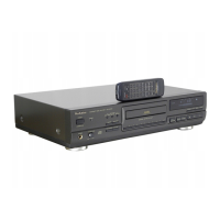
Lists essential accessories provided with the unit, like power cords.
Guides on connecting the CD player to amplifiers and other audio equipment.
Instructions for replacing the fuse and correct wiring of the AC mains lead in the UK.
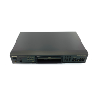
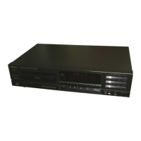
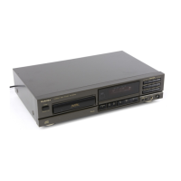
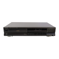
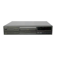
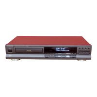
Identifies and describes the functions of buttons and indicators on the front panel.
Step-by-step guide to play a CD from start to finish.
Steps to remove the outer cabinet and front panel assembly.
Procedures for removing the main PCB and power switch PCB.
Steps to remove the operation PCB and the loading unit.
Procedures for removing the power supply PCB and spacer.
Steps to remove the disc tray, servo PCB, and flexible cables.
Procedures for removing the unit's feet and other minor parts.
Steps to remove the traverse deck assembly and converter lever.
Procedures for removing the lock lever and gear cover.
Steps to remove the loading motor PCB, slide plates, and disc tray ornament.
Steps to remove the main traverse deck and drive rack.
Detailed steps for correctly installing the disc tray into the mechanism.
Guidelines for properly disposing of wires during service.
Steps for checking the functionality and connections of the main circuit board.
Steps for checking and adjusting the servo printed circuit board.
Visual representation of the main functional blocks and their interconnections.
Detailed circuit diagrams for the optical pickup and servo control systems.
Circuit diagrams for the main control, operation, and power supply sections of the unit.
Visual layouts showing component placement and routing on various printed circuit boards.
Illustrates how different components and PCBs are interconnected via wiring harnesses.
Procedure to access and interpret error codes for diagnosing servo circuit issues.
Explanation of the digital servo system and its operational flow.
A guide to identify and resolve common operational problems using flowcharts and symptom analysis.
Detailed list of terminal functions for key integrated circuits used in the unit.
Comprehensive list of replaceable parts with their part numbers and descriptions.
Diagrams showing the physical location and reference numbers of cabinet parts.
Diagrams illustrating the parts and their arrangement within the disc loading unit.
Details on the materials used for packaging and how the unit is secured.