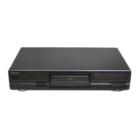
Do you have a question about the Technics SL-PG390 and is the answer not in the manual?
Details about audio performance like channels, frequency response, output voltage, and dynamic range.
General specifications including power consumption, power supply, dimensions, and weight.
Specifications related to the optical pickup, such as wavelength and laser power.
Guidelines for handling the traverse deck, including static electricity precautions and avoiding adjustment.
Procedures for grounding to prevent electrostatic discharge during repair work.
Diagram and notes for connecting the unit to a household AC outlet.
Diagram and notes for connecting to a digital amplifier via optical cable.
Important safety warnings regarding the AC mains lead and plug usage.
Step-by-step instructions and diagrams for replacing the fuse in the mains plug.
Procedure for diagnosing the servo system and displaying error information.
Instructions on how to exit the self-diagnostic mode.
Procedure for diagnosing mechanism control switches and displaying error codes.
Explanation for error code F26 indicating communication error between servo IC and CPU.
Procedures for checking the operation and CD servo P.C.B.s.
Procedures for replacing the traverse unit assembly and loading belt/motor.
Schematic diagram detailing the CD servo circuit and its components.
Schematic diagram illustrating the power switch circuit and related components.
Schematic diagram for the unit's operation circuit, including controls and sensors.
Schematic diagram for the loading motor circuit and its driver.
Schematic diagram of the main circuit board and its interconnected components.
Diagram of the CD servo printed circuit board.
Diagram of the power switch printed circuit board.
Diagram of the loading motor printed circuit board.
Flowchart for diagnosing and resolving issues with CD playback.

