EasyManuals Logo

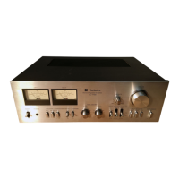
Technics SU-7300 Service Manual

Technics SU-7300
12 pages
To Next Page IconTo Next Page
To Previous Page IconTo Previous Page
Page #5 background imageLoading...
Page #5 background image
m@
ABGLEICHANWEISUNGEN
e
Wenn
der
Netztransistor
ersetzt
wird,
ist
zu
beachten,
dafS
eine
Siliziumverbindung
(
oder
ahnliches
Thermodiffusions-
mittel)
auf
die
Glimmerplatte
gegeben
wird,
und
zur
gleichen
Zeit
der
Blindstrom
des
Netztransistors
festgestellt
wird..
(
Die
Spannung
Uber
den
Emitterwiderstand
messen.)
>
Zum
Justieren
mit
dem
Gleichstrom-Voltmeter
1.
Drehen
Sie
den
Lautsprecherschalter
auf
‘‘OFF’’.
2.
SchlieRen
Sie
den
Gleichstrom-Voltmeter
an,
wie
in
Abb.
7
des
Justrerpunkte-Diagramms
gezeigt.
3.
Falls
die
Anzeige
weniger
als
ca.
25
mV
betragt,
so
ist
die
Schaltung
in
Ordnung.
Falls
aber
die
Anzeige
mehr
als
25
mV
betragt,
sehneiden
Sie
den
Leitungsdraht
fir
L
im
Palle
des
linken
Kanals
weg
(
oder
den
Leitungsdraht
fir
R
im
Falle
des
rechten
Kanals)
.
4
.
Falls
die
Anzeige
auch
nach
Unterbrechen
des
Leitungsdrahtes
nicht
unter
25
mV
fallt,
so
ist
die
Schaltung
nicht
in
Ordnung,
und
die
Stromquellenschaltung
und
die
Hauptverstarkerschaltung
mussen
tiberpruft
werden.
ANMERKUNG:
Falls
das
Wegschneiden
des
Leitungsdrahtes
nétig
ist,
schneiden
Sie
diesen
nahe
am
Anschlufpunkt
weg.
Rm
Die
Stromstarke
sollte
nur
geprift
werden,
wenn
die
Justierung
mit
einem
Prifgerat
vorgenommen
wird.
(Mit
dem
MeRinstrument
kann
die
Spannung
nicht
in
mV
gemessen
werden.)
1.
Schalten
Sie
die
Stromzufuhr
zum
Gerat
aus.
2.
SchlieBen
Sie
das
Ammeter
an,
wie
in
Abb. 9
gezeigt.
3.
Nachdom
Sie
sich
vergewissert
haben,
daf§
das
Ammeter
solide
befestigt
ist,
schalten
Sie
die
Stromzufuhr
ein.
4.
Falls
die
Anzeige
einige
Minuten
nach
dem
Einschalten
weniger
als
75
mA
betragt,
so
ist
die
Schaltung
in
Ordnung.
Liegt
die
Anzeige
Uber
75
mA,
schneiden
Sie
den
Leitungsdraht
fir
L
im
Falle
des
linken
Kanals
weg.
(oder
den
Leitungsdraht
fur
R_
im
Falle
des
rechten
Kanals)
.
5.
Falls
die
Anzeige
auch
dann
nicht
unter
75
mA
fallt,
so
ist
die
Schaltung
defekt.
ANMERKUNG:
Die
Justierung
kann
entweder
nach
Methode
@)
oder
vorgenommen
werden.
(Wo
médglich,
empfehlen
wir
Methode
().
Die
Abbildungen
8
und
9
beziehen
sich
auf
den
linken
kanal.
mw
INSTRUCTIONS
D’ALIGNEMENT
e
Lorsque
Je
transistor
de
puissance
est
remplacé,
s'assurer
d'appliquer
le
composé
de
silicone
(ou
un
agent
de
diffusion
thermique
équivalent)
sur
la
plaque
de
mica
et
confirmer
en
méme
temps
le
courant
déwatté
du
transistor
de
puissance.
(Mesurer
la
tension
a
travers
la
résistance
de
I'émetteur).
aN
+ +
=
A’
Pour
la
mise
au
point
avec
un
voltmétre
C.C.
1.
Tourner
le
commutateur
de
haut-parleur
sur
“OFF’’.
2,
3.
4.
Connecter
te
voltmétre
C.C.
comme
dans
la
Fig.
7
du
schéma
des
endroits
de
vérification.
Si
la
lecture
est
approximativement
inférieure
4
25
mV
plusieurs
minutes
aprés
la
mise
en
marche
de
I‘alimentation,
le
circuit
fonctionne
correctement.
Par
contre,
si
la
lecture
est
au-dela
de
25
mV,
couper
le
fil
de
jonction
pour
L
dans
le
cas
du
canal
Gauche
[L],
(le
fil
de
jonction
pour
R,
dans
le
cas
du
cana!
Droite
[R]).
Si
la
lecture
ne
descends
pas
au-dessous
de
25
mV
méme
lorsque
le
fi!
de
jonction
a
été
coupé,
cela
signifie
qu
il
ya
quelque
chose
d'‘incorrect
dans
le
circuit
et
par
conséquent,
il
sera
nécessaire
de
vérifier
le
circuit
d‘alimentation
ou
le
circuit
d‘amplification
principal.
REMARQUE:
Lorsqu‘on
coupe
le
fil
de
jonction,
le
couper
a
l'extrémité
de
sa
racine.
="
a
eotgee
. .
.
i.
a
.
8
Le
courant
ne
devra
étre
vérifié
seulement
que
lorsque
la
mise
au
point
est
faite
avec
un
appareil
contrdéleur.
(Appareil
de
1.
2.
3.
4.
5.
mesure
incapable
d'une
tension
de
mesure
dans
un
appareillage
de
mV).
Couper
l‘alimentation
de
l’appareillage.
Brancher
l'ampéremétre,
comme
il
est
montré
a
la
Fig.
9.
Apres
s‘étre
assuré
que
l'ampéremétre
n'est
pas
débranché,
mettre
en
marche
I'alimentation.
Si
la
lecture
est
inférieure
a
75
mA
aprés
plusieurs
minutes,
le
circuit
fonctionne
correctement.
Si
par
contre
la
lec-
ture
va
au-dela
de
75
mA,
couper
le
fil
de
jonction
pour
L
dans
le
cas
du
canal
Gauche
[L]
,
(le
fil
de
jonction
pour
R
,
dans
le
cas
du
canal
Droite
[R]).
Si
la
lecture
ne
descends
pas
au-dessous
de
75
mA,
cela
signifie
qu'il
y
a
quelque
chose
de
défectueux
dans
le
circuit.
REMARQUE:
La
mise
au
point
doit
étre
faite
soit
avec
la
méthode
@),
soit
avec
la
méthode
‘B.
(Si
c'est
possible,
nous
recommandons
la
méthode
@).
Les
Figures
8
et
9
se
rapportent
au
cas
du
canal
Gauche
[L]
.
SU-7300
[5]
m@
SERVICE
AID
Shock
noise
prevention
circuit
during
ON-OFF
of
power
supply
In
the
voltage
at
the
point
@,
at
he
moment
when
the
power
supply
is
turned
ON,
C302
is
ch.irged
by
the
current
rectified
to
negative
through
D301.
Therefore,
gradual
change
to
minus
takes
place
from
OV.
During
this
time,
positive
voltage
is
applied
to
the
base
of
TR301
which
is
thus
rendered
conductive.
Consequently,
the
base
of
TR302
connected
to
TR301
is
of
ground
potential,
with
TR302
not
being
functioning.
!n
other
words,
no
current
is
Howing
through
the
preamplifier
in
this
state.
After
the
power
supply
is
turned
ON,
the
potential
at
the
point
®
gradually
decreases
as
the
point
Ais
saturated
to
negative
through
time
constant
of
R302
and
C302,
and
when
TR301
reaches
cut-
off
state,
positive
voltage
goes
on
charging
C303.
Upon
rising
of
the
base
potential!
of
TR302
close
to
0.7V,
TR302
is
turned
ON,
thus
causing
current
to
flow
through
the
preamplifier.
Time
required
from
turning
ON
of
the
power
supply
to
functioning
of
the
preamplifier
is
set
to
be
approximately
6
to
7
seconds.
When
the
power
supply
is
turned
OFF,
D302
is
biased
in
the
forward
direction,
and
if
R301<R302,
the
charges
in
C301
and
C302
are
discharged
through
R301
in
a
short
period
of
time.
However,
large
positive
voltage
of
specific
constant
does
not
fall
immediately,
with
voltage
at
the
point
®)rising
up
to
TR301
operating
voltage
for
causing
TR301
to
function.
Accordingly,
the
charge
in
C303
is
discharged,
and
TR302
rapidly
reaches
cut-off
state,
with
current
being
prevented
from
flowing
through
the
preamplifier,
so
that
the
shock
noises
from
the
preamplifier
section
during
turning
OFF
of
the
power
supply
can
be
eliminated.
D303
TR302
OC
39V
Large
Time-Constant
To
emitter
of
Rch.
initial
stage
differential
amplifier,
To
emitter
of
Lch,
initial
stage
differential
amplifier.
Rch,
pre-driver
stage
power
source.
Lch,
pre-driver
stage
power
source,
m@
BLOCK
DIAGRAM
[uert
|
ON
é
EQUALIZER
9
$2
(SELECTOR)
ews
?
(HIGH
FILTER)
=
ory
OFF
ON
$8
(SPEAKERS)
q
1
|
ON
1
b
i
TUNER@————“
|
s1
i
@
MAIN
?
|
FUSE
OFF
POWER
5
oe
(LEFT)
een
|
|
i
L_—e
remote
7;
I
1
™r
REC
OUT
E—4
2
©S3(TAPE
MONITOR)
ri
HEADPHONES
uJ
ros
©
Q
|
g
METER
;
-
*
PLAYBACK
r
=
MUTING
LN
MAIN
2
RIGHT)
(
t_e
REMOTE
39
1
“REC
OUT
G
j
3
bu
2
:[
i
-
F
PLAYBACK
©
ge
4
1,
|
S4(REC
MODE)
(TAPE
1)
(63
2.9
necro
_
|
zi
1
[REC
PLAY.
alee
Ein
orr
“A,
on
°
$5
(LOUDNESS)
[6]
SU-7300

Other manuals for Technics SU-7300

Questions and Answers:

Question and Answer IconNeed help?

Do you have a question about the Technics SU-7300 and is the answer not in the manual?

Technics SU-7300 Specifications

General IconGeneral
Damping Factor30
Speaker Load Impedance4Ω to 16Ω
Input Sensitivity2.5mV (MM)
Signal to Noise Ratio90dB (line)
Channel Separation55dB (line)
Output150mV (line)

Related product manuals