EasyManuals Logo

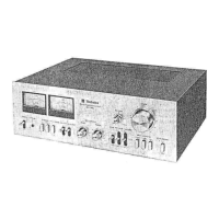
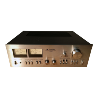
Technics SU-7300 Service Manual

Technics SU-7300
12 pages
To Next Page IconTo Next Page
To Previous Page IconTo Previous Page
Page #4 background imageLoading...
Page #4 background image
@
NOTE
The
unit
is
provided
with
the
speaker
circuit
protection
fuses
at
the
right
and
left
channels
respectively.
The
fuse
is
to
prevent
the
power
transistor
from
destruction,
should
the
speaker
terminals
be
short-circuited.
Accordingly,
if
the
unit
fails
to
function
upon
completion
of
the
speaker
connections,
check
the
speaker
protection
fuses
first
of
all
for
possible
blowing.
w
ALIGNMENT
INSTRUCTIONS
e
When
the
power
transistor
is
replaced,
be
sure
to
apply
silicone
compound
(or
equivalent
thermal
diffusion
agent)
onto
the
mica
plate,
and
at
the
same
time
confirm
the
idling
current
of
the
power
transistor.
(measure
voltage
across
the
emitter
resistance)
For
adjustment
with
DC
voltmeter
.
Turn
the
speaker
switch
“OFF”.
_
Connect
the
DC
voltmeter
as
in
Fig.
7
of
the
adjusting
spot
diagram.
_
If
the
reading
is
under
25mV
approximately
several
minutes
after
turning
ON
the
power
supply,
the
circuit
is
“OK”.
On
the
other
hand,
if
the
reading
is
over
25mV,
cut
off
the
lead
wire
for
L
inthe
case
of
left
channel
(The
lead
wire
for
R
in
the
case
of
right
channel).
4.
Should
the
reading
not
fall
under
25mV
even
when
the
lead
wire
has
been
cut
off,
there
is
something
wrong
with
the
circuit,
and
therefore,
check
the
power
source
Circuit
or
main
amplifier
circuit.
Oon—-&
NOTE:
When
cutting
off
the
lead
wire,
cut
off
the
same
at
the
root.
®
Current
should
be
checked
only
when
adjustment
is
made
with
a
tester.
(measuring
instrument
incapable
of
measur-
ing
voltage
in
mV
unit).
.
Turn
OFF
the
power
supply
for
the
set.
.
Connect
the
ammeter
as
shown
in
Fig.
9.
.
After
ensuring
that
the
ammeter
will
not
come
off,
turn
ON
the
power
supply.
.
If
the
reading
is
under
75mA
after
serveral
minutes
(But,
when
nothing
resistance
of
internal
resistor
by
ammeter)
the
circuit
is
"OK".
If
over
75mA,
cut
off
the
lead
wire
for
L
in
the
case
of
left
channel
(The
lead
wire
for
R
in
the
case
of
right
channel).
5.
If
the
reading
does
not
fall
under
75mA,
there
is
something
wrong
with
the
circuit.
BWOWN
>
NOTE:
The
adjustment
may
be
made
either
by
@)
or
by
(B
method.
(We
recommend
the
method
‘®
where
possible).
Figs.
8
and
9
are
related
to
the
case
of
left
channel.
+B
DC
VOLTMETER
+B
DC
AMMETER
TP204]
[TP202
R
ch.
Less
than
OC
25
mv
L
ch,
Less
than
OC
25mvV
Voitage
check
method
Current
check
method
(Stromspannung-priifmethode)
(Stromstarke-Priifmethode)
Méthode
de
vérification
Méthode
de
vérification
de
tension
de
courant
Fig.
7
(Abb.
7)
Fig.
8
(Abb.
8)
Fig.
9
(Abb.
9)
[4]
SU-7300

Other manuals for Technics SU-7300

Questions and Answers:

Question and Answer IconNeed help?

Do you have a question about the Technics SU-7300 and is the answer not in the manual?

Technics SU-7300 Specifications

General IconGeneral
Damping Factor30
Speaker Load Impedance4Ω to 16Ω
Input Sensitivity2.5mV (MM)
Signal to Noise Ratio90dB (line)
Channel Separation55dB (line)
Output150mV (line)

Related product manuals