Home
Technics
Amplifier
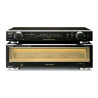
SU-C800U
Technics SU-C800U Service Manual
4.5
of 2
of 2 ratings
17 pages
Give review
Manual
Specs
To Next Page
To Next Page
To Previous Page
To Previous Page
Loading...
|
SU-C800U
Mi
Operation
Check
and
Main
Component
Replacement
Procedures
\lezi=§
61.
This
section
describes
procedures
for
checking
the
operation
of
the
major
printed
circuit
boards
and
replacing
the
main
components.
2.
For
reassembly
after
operation
checks
or
replacement,
reverse
the
respective
procedures.
Special
reassembly
procedures
are
described
only
when
required.
3.
Illustrated
screws
are
equivalent
to
actual
size.
1.
Checking
for
the
operation
P.C.B.
and
main
P.C.B.
(x
or
©
(Black)
([RHD30035-K1
]
()
OOD
©,©
(Black)
(XTBS3+8JFZ1]
Remove
the
cabinet.
()
ED
©
(Black)
|
(XTB3+20JFZ)
oa
Operation
P.C.B.
¢
Check
the
operation
P.C.B.
this
condition.
Connect
the
lead
wire.
~
~~
GND
plate
Main
P.C.B.
«
Check
the
main
P.C.B.
as
shown
above.
2
4
Table of Contents
Main Circuit
6
Operation Circuit
8
Printed Circuit Board Diagram
10
Wiring Connection Diagram
12
4.5
Based on 2 ratings
Ask a question
Give review
Questions and Answers:
Need help?
Do you have a question about the Technics SU-C800U and is the answer not in the manual?
Ask a question
Technics SU-C800U Specifications
General
Type
Stereo Amplifier
Input Sensitivity
150mV (Line)
Damping Factor
60 (8 Ohm, 1 kHz)
Speaker Load Impedance
4 - 16 Ohm
Channel Separation
65dB (1kHz)
Related product manuals
Technics SU-C800UM2
18 pages
Technics SU-C01
12 pages
Technics SU-C1000
32 pages
Technics SU-C1010
42 pages
Technics SU-CH700
23 pages
Technics SU-V6
10 pages
Technics su-g86
20 pages
Technics SU-600
20 pages
Technics su-g70
20 pages
Technics SU-700
19 pages
Technics SU-500
20 pages
Technics SU-A600
25 pages