EasyManua.ls Logo

Technics SU-X101

Technics SU-X101
20 pages
To Next Page IconTo Next Page
Loading...
ORDER
NO.
AD9002026C8
Service
Manual
Amplifier
Stereo
Integrated
Amplifier
S
U
-
x
1
0
1
/
S
U
:
X
2 0
1
Color
|(K)...Black
Type
|
Area
Country
Area
Code
Continental
Europe
B
Great
Britain
F.R.Germany
&
Italy
Asia,
Latin
America,
(GC)
Middle
Near
East
and
Africa
SPECIFICATIONS
(DIN
45
500)
AMPLIFIER
SECTION
Muting
—20
dB
DIN
power
output
2x40
W
(8Q)
(SU-X101)
Super
bass
70
Hz,
O~
+10
dB
1kHz
THD:
1%
2x50
W
(8Q)
(SU-X301)
Output
voltage
TAPE
REC
OUT
200
mV
Total
harmonic
distortion
Channel
balance,
AUX
250
Hz~6,300
Hz
+1.0
dB
rated
power
at
1
kHz
1%
(8
Q)
Channel
separation,
AUX
1
kHz
55
dB
Harmonic
distortion
Headphones
output
level
and
impedance
473
mV/330
Q
half
power
at
1
kHz
0.03
%
(8Q)
Load
impedance
Residual
hum
and
noise
0.5
mV
MAIN
8Q~160
Damping
factor
30
(8
Q)
SURROUND
8O~160
Input
sensitivity
and
impedance
PHONO
3
mV/47
kQ
TUNER,
AUX,
TAPE
200
mV/22
kQ
W@
GENERAL
CD
300
mV/15
kQ
Maximum
input
voltage
(1
kHz,
RMS)
Power
consumption
330
W
PHONO
120
mV
Power
supply
S/N
(rated
power
8
©)
For
Great
Britain
and
Oceania:
AC
50
H2/60
Hz,
240
V
PHONO
73
dB
(IHF,
A:
79
dB)
For
continental
Europe,
F.R.
Germany
and
Italy:
TUNER,
CD,
AUX,
TAPE
84
dB
(IHF,
A:
83
dB)
AC
50
Hz/60
Hz,
220
V
Frequency
response
For
others:
AC
50
Hz/60
Hz,
110
V/127
V/220
V/240
V
PHONO
RIAA
standard
curve
Dimensions
(W
x
H
x
D)
360
x
106.2
x
304
mm
oan
+0.8
dB
(30
Hz~15
kHz)
(14-3/16"
x
4-3/16"
x
12”)
:
ER,
CD,
AUX,
TAPE
15
Hz~50
kHz
(—3
dB)
Weight
5.3
kg
(11.7
Ib.)
one
controls
BASS
50
Hz,
+10
dB~—10
dB
Note:
pRERSS
SU
ne
ae
wee
Total
harmonic
distortion
is
measured
by
the
digital
spectrum
analyzer.
‘Technics
Matsushita
Electric
Industrial
Co.,
Ltd.
Central
P.O.
Box
288,
Osaka
530-91,
Japan
Question and Answer IconNeed help?

Do you have a question about the Technics SU-X101 and is the answer not in the manual?

Technics SU-X101 Specifications

General IconGeneral
Frequency response5Hz - 100kHz (±1dB)
Total harmonic distortion0.005% (1kHz, 8Ω)
Dimensions430 x 125 x 310mm
Weight12.5kg
Input sensitivity150mV (line)

Summary

Amplifier Specifications

Amplifier Section Details

Technical specifications including power output, distortion, and input sensitivity.

General Unit Specifications

Overall unit details like power supply, dimensions, and weight.

Pre-Repair and Safety Procedures

Before Repair Safety Checks

Procedures for safely discharging capacitors and checking current.

Protection Circuitry and Troubleshooting

Explanation of protection circuitry function and activation troubleshooting.

Included Accessories List

List of accessories provided with the unit.

Control Panel Layout and Functions

Front Panel Controls and Indicators

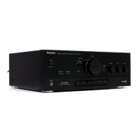
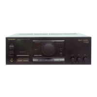
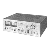
Identification and purpose of all front panel controls.

Rear Panel Connections and Features

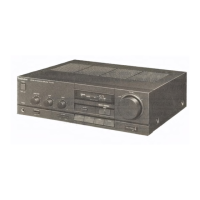
Overview of rear panel terminals and connectors.

System Connectivity Guide

Connecting to Cassette Deck

Instructions for connecting the amplifier to a cassette deck.

AC Power Supply Connection

Guidance for connecting the AC power cord, noting area variations.

Connecting Other Audio Sources

Turntable, Tuner, and CD Player Connections

Connecting primary audio sources via dedicated terminals.

AUX and External Device Connections

Connecting auxiliary devices and external equipment like graphic equalizers.

Disassembly Procedures - Exterior

Cabinet and Front Panel Removal

Steps for removing the outer cabinet and front panel.

Power Switch and Volume PCB Removal

Procedures for disassembling the power switch and volume control PCBs.

Disassembly Procedures - Internal Components

Power Supply and Fan Motor Removal

Instructions for removing the AC outlet, fan motor, and transformer.

Main PCB and Power IC Removal

Procedures for removing the main PCB, power IC, and regulator transistor.

Service and Maintenance Notes

Servicer Safety Precautions

Important warnings for technicians regarding component handling.

Foot Replacement Guide

Step-by-step instructions for replacing the unit's feet.

System Block Diagram

Audio Signal Path Overview

Visual representation of signal flow and functional blocks within the amplifier.

Printed Circuit Board Layouts (Part 1)

Main and InputOutput PCBs Layout

Layout diagrams for the main and input/output terminal PCBs.

Volume and Power Switch PCBs Layout

Layout diagrams for the volume control and power switch PCBs.

Printed Circuit Board Layouts (Part 2)

Phono EQ and FL Drive PCBs Layout

Layout diagrams for the phono equalizer and FL drive/tone amplifier PCBs.

AC Outlet and Input Select PCBs Layout

Layout diagrams for AC inlet/outlet and input select PCBs.

Component Pinout Guide

IC, Transistor, and Diode Terminal Identification

Detailed pin assignments for various electronic components.

Internal Wiring Diagram

PCB Interconnection and Wiring Layout

Diagram showing internal wiring between PCBs and external connections.

Front Panel Display and IC Functions

FL Panel Grid and Pin Assignments

Details on the FL display's grid layout and pin connections.

Microcomputer IC Terminal Functions

Description of functions for each pin of the main microcomputer IC.

SU-X101 Replacement Parts - ICs and Transistors

SU-X101 Integrated Circuits

List of ICs with part numbers and descriptions for SU-X101.

SU-X101 Transistors

List of transistors with part numbers and descriptions for SU-X101.

Exploded View of Unit Assembly

Component Breakdown Diagram

Illustrated exploded view showing unit assembly and numbered parts.

SU-X101 Replacement Parts - Passive Components

SU-X101 Cabinet Parts and Hardware

List of cabinet parts, screws, nuts, and hardware for SU-X101.

SU-X101 Resistors and Capacitors

Detailed list of resistors and capacitors for SU-X101.

SU-X301 Replacement Parts - ICs and Capacitors

SU-X301 Integrated Circuits and Transistors

List of ICs and transistors with part numbers for SU-X301.

SU-X301 Capacitors and Diodes

List of capacitors and diodes with part numbers for SU-X301.

SU-X301 Replacement Parts - Cabinets and Resistors

SU-X301 Cabinet Parts and Connectors

List of cabinet parts, connectors, and hardware for SU-X301.

SU-X301 Resistors and Fuses

Detailed list of resistors and fuses for SU-X301.

SU-X301 Replacement Parts - Capacitors and Resistors

SU-X301 Capacitor Values Detailed

Comprehensive list of SU-X301 capacitors and their values.

SU-X301 Resistor Values Detailed

Detailed list of SU-X301 resistors and their values.

Related product manuals