EasyManuals Logo

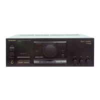
Technics SU-X955 Service Manual

Technics SU-X955
26 pages
To Next Page IconTo Next Page
To Previous Page IconTo Previous Page
Page #19 background imageLoading...
Page #19 background image
m@
FUNCTIONS
OF
IC
TERMINALS
#1C601
(M50754-411SP)
MICRO
COMPUTER
For
ground
connection.
Inputs
data
from
the
remote
controller.
ee
i
Terminal
Pin
No.
th
vo
Name
Function
1
I
Voo
To
be
connected
to
a
power
supply.
b
2
oO
LcD
This
is
the
output
terminal
for
the
LED
selector
indicator
of
the
CD
player.
Ata"HI"
level
........
the
LED
lights
up.
|
3
_—_
cs2
For
ground
connection.
4
VAI
I
These
are the
terminals
for
the
rotary
encoder
of
the
volume
of
VR601.
5
vRO
6
oO
PWM
This
terminal
outputs
the
signal
for
the
control
of
the
volume
and
balance
7
!
REC
This
is
the
terminal
for
the
detection
of
recording
on
the
deck.
a
}.
8
ré)
SY
OUT
This
is
the
terminal
for
synchro
recording
on
the
deck.
9
|
DECK
This
is
the
terminal
for
direct
operations
on
the
deck.
10
(
CDE
Outputs
the
signal
for
the
control
of
CD
editing.
W
co
(
These
are
the
terminals
for
the
start
of
synchronization
on
the
CD
unit.
12
CD.
SY.
13
|
PL.
SY.
14
ie)
PL.
START
These
are
the
terminals
for
sync
recording
on
the
player.
15
fe)
PL.
STOP
16
DATA
CLK:
This terminal
outputs
the
clock
signal
for
reading
serial
data.
DATA:
This
terminal
outputs
the
serial
data.
17
fe)
CLK
STB:
This
terminal
outputs
the
pulse
for
the
control
of
the
setting
of
the
analog
switch.
The
serial
data
inputted
into
1C201
is
latched
by
the
STB
pulse
and
the
18
STB
switch
is
set
to
ON
according
to
data.
Outputs
the
signal
for
the
control
of
SURROUND.
Ng
2
SURR
|
ata
“LOW’
level
.....
SURROUND
is
ON.
20
°
$.T0U
Outputs
the
signal
for
the
control
of
SUPER
DYNAMIC
SOUND.
Ata
"“LOW'
level
......
SUPER
DYNAMIC
SOUND
is
ON.
21
ie)
MUT
1
Outputs
the
signal
for
the
control
of
muting.
22
SYNOUT
2
|
Unused.
23
(e)
MUTE
Outputs
the
—6
dB
signal
for
the
control
of
attenuated
muting.
24
i
HAC
This
is
the
terminal
for
the
detection
of
power
supply.
Ata
“HI"
levet
the
LEO
lights
up.
27
(
RESET
This
terminal
inputs
the
reset
signal.
28
I
XIN
These
are
the
I/O
terminals
for
the
oscillating
clock
signal.
29
ie}
X
OUT
L
a
4
30
Xc
IN
——
Unused.
3
Xc
OUT
te
4
32
Vss
For
ground
connection.
33
—=
NC
Unused.
|
35
so
D
35
36]
37
i
re)
t
SUPER
37
$2
nese
are
the
61
{DYNAMIC
|
——
TAPE
key
matrix
SOUND
61
Ko
terminals
for
.62__
[SURROUND]
DAT.
|
cD
|
?
|
?
input
selection.
63_|
MUTING
|
vO
|
TUNER
|
64
K3
6a
|
——
[|
vrr_
|
PHONO
|
38
!
Ve
The
signal
which
pulls
down
the
voltage
is
inputted
into
this
terminal.
39
$3
a t
46
$10
These
terminals
output
the
signals
for
the
control
of
the
multi-digital
QO
GO
49
display.
i H
52
G3
Outputs
the
signal
for
the
control
of
the
TAPE
LED.
53
°O
LTAPE
|
Ata“Hi"level
........
the
LED
lights
up.
Outputs
the
signal
for
the
control
of
the
VTR
LED.
oA
°
ae
Ata“Hi"
level
........
the
LEO
lights
up.
55
oO
Lvp
Outputs
the
signal
for
the
control
of
the
VD
LED.
-25-
Terminal
Pin
No.
vo
Name
Function
Outputs
the
signal
for
the
control
of
the
TUNER
LED.
|
56
°
EXUNER
Ata“Hi"
level
........
the
LED
lights
up.
+
Outputs
the
signal
for
the
control
of
the
PHONO
LED.
me
©
LPHONO
J
ata"Hl
level
........
the
LED
lights
up.
Outputs
the
signal
for
the
control
of
the
DAT
LED.
3b
7
EDAE
Ata“Hi"
level
......
.
the
LED
lights
up.
59
°
VTR
Outputs
the
signal
for
muting
the
VTR
recording.
REC
MUTE
}
Outputs
the
signal
for
the
control
of
the
MUTING
LED.
20
©
EMUTE
Ata“Hl"
level
........
the
LED
lights
up.
©1C806
(YM3623B)
DIGITAL
INTERFACE
RECEPTION
(PU)
terminals
are
“pulled
up”.
=
Pin
No.
oe
vo
Function
la
i
alee
1
VDD1
This
is
the
power
connection
terminal
(+5
V).
2
ADJ
t
This
terminal
is
for
the
adjustment
of
the
VCO
oscillation
frequency,
but
it
is
not
used
in
this
unit
3
vco
vO
This
is
the
external
condenser
terminal
for
the
VCO
circuitry.
4
VSS2
—_
This
is
the
ground
connection
terminal
of
the
system.
5
xo
fe]
This
is
the
output
terminal
for
the
crystal
vibrator
(16.9344
MHz).
|
6
xl
I
This
is
the
input
terminal
for
the
crystal
vibrator
;
7
KMODE
1(PU),
Ata
high
level...the
PLL
circuitry
is
activated
when
the
DIN
terminal
receives
an
input
signal
Otherwise,
the
crystal
vibrator
is
activated
i
Ata
low
level...the
crystal
vibrator
is
activated,
regardless
of
the
DIN
terminal
input
8
BA
fe)
This
terminal
outputs
a
16.9344-MHz
frequency
when
the
crystal
vibrator
functions.
When
the
PLL
,
Circuitry
is
activated,
the
frequency
varies
according
to
the
speed
of
input
data
of
the
DIN
terminal
'
(fs=about
16.9344
MHz
when
it
is
44.2
kHz).
{_——-
{
9
@B
°
The
frequency
of
this
terminal
is
divided
into
a
third
of
that
of
terminal@A
when
the
crystal
vibrator
!
functions.
When
the
PLL
circuitry
is
activated,
the
frequency
varies
according
to
the
speed
of
input
data
|
of
the
DIN
terminal
(fs=about
16.9344
when
itis
44.2
kHz).
——————
5
ieee
z|
10
1
1(PU)
This
is
the
input
terminal
for
checking
the
internai
circuitry.
|
a
fi
ie
tT
"1
T2
1
(PU)
This
is
the
input
terminal
for
checking
the
internal
circuitry.
12
BCO
ie}
Used
to
output
the
time-clock
signal
from
the
DO
terminal.
-+
+
13
SYNC
[e)
i
Used
to
output
the
synchronization
signal.
14
VSS1
This
is
the
ground
connection
terminal
of
the
system
(+0
V).
15
UR
°
At
a
high
level...data
on
the
left
channel
is
output
from
the
DO
terminal.
At
a
low
level...data
on
the
right
channel
is
output
from
the
DO
terminal.
16
DEF
ce}
At
a
high
level...input
data
is
emphasized.
At
a
low
level...input
data
is
not
emphasized.
a
i
AZ
DO
re]
Outputs
16-bit
data.
18
WC
ie)
This
is
the
terminal
for
checking
data
output
to
the
DO
terminal.
=
19
DIGR
(¢}
This
terminal
outputs
the
signal
for
the
right
channel.
20
DIGL
ie]
This
terminal
outputs
the
signal
for
the
left
channel.
21
ERR
re)
Error
detection
terminal.
H=Error
is
found
during
parity
check
+L=No
errors
22
+
SEL
23
S1
24
$2
=
—<f
25
SCK
fe)
Terminal
for
the
clock-signal
of
the
sub
code
output.
4
26
SSYNC
ie]
For
the
signal
of
the
sub
code.
27
$DO
oO
For
the
output
of
sub
code
data.
:
eee
28
DIN
1(PU}
[Fe
the
input
of
data.
|
-26-
#1C806
(YM3404B)
Digital
filter
cae
Mark
vo
Function
H
1
Ai
a
;
re)
1DAC(ST
=
“L"):
Leh
Deglitcher
signal
2DAC{ST
=H"):
L/Reh
Deglitcher
signal
}
2
xO
O
|
Clock
output
-
—_
=|
3
x1
z
Clock
input
7
7
[4
vope
I
Power
supply
(couneeiad
to
+5V)
5
BCI
1
Bit
clock
input
(input
data)
-
6
SDSY
{
|
R/L
signal
7
SDI
4
Data
input
8
VDD1
{
Power
suppty
(connected
to
+
5V)
9
crs
oO
TIDAC(ST
=
“L”):
L/Ach
data
output
terminal
2DAC(ST
="H"):
Lch
data
output
terminal
“to
RDO
O
|
Rch
data
output
(not
connected)
tt
WCO.
©
|
Output
data
word
clock
|
2
BCO
O
|
Bit
clock
output
(output
data)
13
vss
!
|
GND
terminal
|
14
st
'
IDAC/2DAC
selector
terminal
|
15
FEN
!
System
clock
selector
terminal
16
SHR
oO
L
IDAC(SP="L”):
Reh
deglitch
signal

Questions and Answers:

Question and Answer IconNeed help?

Do you have a question about the Technics SU-X955 and is the answer not in the manual?

Technics SU-X955 Specifications

General IconGeneral
BrandTechnics
ModelSU-X955
CategoryAmplifier
LanguageEnglish

Related product manuals