EasyManuals Logo

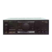
Technics SU-X955 Service Manual

Technics SU-X955
26 pages
To Next Page IconTo Next Page
To Previous Page IconTo Previous Page
Page #20 background imageLoading...
Page #20 background image
Function
al
for
the
control
of
the
TUNER
LED.
ate
te
the
LED
lights
up.
al
for
the
control
of
the
PHONO
LED.
es
the
LED
lights
up.
al
for
the
control
of
the
DAT
LED.
ee
the
LED
lights
up.
al
for
muting
the
VTR
recording.
al
for
the
control
of
the
MUTING
LED.
gg
dete
the
LEO
lights
up.
>E
RECEPTION
(PU)
terminais
are
“pulled
up”.
7
Function
nection
terminal
(+5
V).
2
adjustment
of
the
VCO
oscillation
frequency,
but
it
is
not
used
in
this
unit
denser
terminal
for
the
VCO
circuitry.
nection
terminal
of
the
system.
inal
for
the
crystal
vibrator
(16.9344
MHz).
nal
for
the
crystal
vibrator.
LL
circuitry
is
activated
when
the
DIN
terminal
receives
an
input
signal.
wise,
the
crystal
vibrator
is
activated.
/stal
vibrator
is
activated,
regardless
of
the
DIN
terminal
input.
@
16.9344-MHz
frequency
when
the
crystal
vibrator
functions.
When
the
PLL
he
frequency
varies
according
to
the
speed
of
input
data
of
the
DIN
terminal
Hz
when
it
is
44.2
kHz).
ee
ee
ae
|
terminal
is
divided
into
a
third
of
that
of
terminal
@A
when
the
crystal
vibrator
LL
circuitry
is
activated,
the
frequency
varies
according
to
the
speed
of
input
data
=
about
16.9344
when
it
is
44.2
kHz).
nal
for
checking
the
internal
circuitry.
nal
for
checking
the
internal
circuitry.
e-clock
signal
from
the
DO
terminal.
Ichronization
signal.
nection
terminal
of
the
system
(+0
V).
an
the
left
channel
is
output
from
the
DO
terminal.
n
the
right
channel
is
output
from
the
DO
terminal.
data
is
emphasized.
lata
iS
not
emphasized.
checking
data
output
to
the
DO
terminal.
the
signal
for
the
right
channel.
the
signal
for
the
left
channel.
al,
H=Erroris
found
during
parity
check
L=No
errors
-signai
of
the
sub
code
output.
ib
code.
ode
data.
-26-
e@1C806
(YM3404B)
Digital
filter
Pin
No.
Mark
vo
Function
Eats!
2
Hr}
LiReh
Begitener
signal
2
xo
O
|
Clock
output
~
3
x1
(
Clock
input
4
VDD2
1
Power
supply
(connected
to
+
5V)
5
BCI
|
|
Bit
clock
input
(input
data)
~
6
SDSY
4
R/L
signal
,
7
SDI
t
Data
input
8
vDD1
|
Power
supply
(connected
to
+
5V)
9
DLO
oO
1DAC(ST
="L”):
L/Rch
data
output
terminal
2DAC(ST
=H"):
Lch
data
output
terminal
10
RDO
O
|
Rch
data
output
(not
connected)
W
WwCcO
©
|
Output
data
word
clock
12
BCO
O
|
Bit
clock
output
(output
data)
13
vss
i
:
GND
terminal
14
ST
|
|
1DAC/2DAC
selector
terminal
15
FEN
|
System
clock
selector
terminal
[
16
SHR
°
IDAC{(SP
=”L”):
Rch
deglitch
signat
4
m@
RESISTORS
AND
CAPACITORS
Notes
:
*
Important
safety
notice
:
Components
identified
by
A\
mark
have
special
characteristics
important
for
safety.
When
replacing
any
of
these
components
use
only
manufacturer’s
specified
parts.
*
Bracketed
indications
in
Ref.
No.
columns
specify
the
area.
(Refer
to
the
first
page
for
area.)
Parts
without
these
indications
can
be
used
for
all
areas.
Resistor
Type
Wattage
Numbering
System
For
Resistors
Exampie:
ERD
25
F
J
102
Type
Wattage
Shape
Tolerance
Value
(1/4W)
(KO)
ERX
2
AN
J
471
Type
Wattage
Shape
Tolerance
Value
(2W)
(470)
Numbering
System
For
Capacitors
Example:
ECKD
1H
402
Zz
F
Type
Voltage
Value
Tolerance
Unique
(50V)
(0.001
pF)
ECEA
50
M
330
Type
Voltage
Characteristics
Value
(50V)
(33,1F)
@
Capacity
values
are
in
microfarads
(UF)
unless
specified
otherwise,
P=Pico-farads
(pF)
F=Farads
(F).
@
Resistance
values
are
in
ohms
(Q),
unless
specified
otherwise,
1K
=
1,0000,
1M=
1,000kQ
EROSZTJATI
ERDS2T
J471
ERDS2T
J224
ERDS2T
J224
ERDS2T
J331
ERDS2T
J331
ERDS2T
J473
ERDS2T
J563
ERDS2T
J473
ERDS2T
J563
ERDS2T
J331
ERDS2T
J331
ERDS2T
J680
ERDS2T
J680
ERDS2T
J184
ERDS2T
J184
ERDS2T
J123
ERDS2TJ123
ERDS2T
J104
ERDS2T
J104
ERDS2TJ102
ERDS2T
J102
ERDS2T
J822
ERDS2T
J822
ERDS2TJ102
ERDS2TJ102
ERDS2TJ102
ERDS2TJ102
ERDS2TJ471
ERDS2T
J471
ERDS2T
J182
ERDS2T
J182
ERDS2T
J472
ERDS2T
J472
:
Carbon
:
Metal
Oxide
:
Fuse
Type
Metal
:
Metal
Film
:
Carbon
(chip)
:
Metal
Film
(chip)
:
Solid
:
Incombustible
Box-Shaped
:
Wire-Wound
:
Chip
Resistor
:
Chip
Resistor
:
Electrolytic
;
Ceramic
:
Ceramic
Capacitor
:
Polyester
:
Potypropylene
:
Ceramic
:
Non
Polar
Electrolytic
:
Ceramic
(Chip
Type)
:
Ceramic
(Chip
Type)
:
Semiconductor
:
Liquid
electrolyte
ERDS2TJ102
ERDS2TJ102
ERDS2T
J&21
ERDS2T
J&21
ERDS2TJ102
ERDS2TJ102
ERDS2T
J3a2
ERDS2T
J3a2
ERDS2T
J332
ERDS2T
J332
ERDS2TJ122
ERDS2T
J223
ERDS2T
J223
ERDS2T
J223
ERDS2T
J152
ERDS2TJ162
ERDS2FJ102
ERDS2TJ108
ERDS2TJ108
ERDS2TJ103
ERDS2T
J224
ERDS2T
J224
ERDS2T
104
ERDS2T
J104
ERDS2T
J331
ERDS2T
J331
ERDS2T
J224
ERDS2T
J224
ERDS2T
J223
ERDS2T
J223
ERDS2T
J223
ERDS2T
J223
ERDS2T
J332
ERDS2T
J332
ERDS2T
J223
ERDS2T
J383
ERDS2T
J223
ERDS2T
J393
ERDS2T
J223
ERDS2T
J223
ERDS2T
223
ERDS2T
J822
double
layer
capacitor
RRNSRERGQRNNRRSSBBSSSS
rs
-27-
16.3V
1
16V
:
50V
:
50V
:
500V
+
100V
:
400V
AC
1
125V
AC
(UL)
12:
V2W
25:
1/4W
18:
1/8W
$1:
1/2W
50:
1/2W
3A:
3W
8G
:
1/8W
TA:
10V
1E
:
26V
WW
:
35V
05
:
SOV
2A:
100V
J:
63V
ERDS2T
J562
ERDS2TJ123
ERDS2T
J224
ERDS2T
J332
ERDS2T
J332
ERDS2T
J32
ERDS2T
J382
ERDS2T
J392
ERDS2TJ104
ERDS2T
J104
ERDS2T
Ji22
ERDS2T
J105
ERDS2T
J334
ERDS2T
J103
ERDS2T
J103
ERDS2TJ103
ERDS2TJ103
ERDS2T
J122
ERDS2T
J122
ERDS2T
J392
ERDS2T
J382
ERDS2T
J103
ERDS2T
J103
ERDS2T
J273
ERDS2T
J273
ERDS2T
J103
ERDS2TJ103
ERDS2T
J122
ERDS2T
J223
ERDS2T
J223
ERDS2T
J563
ERDS2T
J563
ERDS2T
J333
ERDS2T
J333
ERDS2TJ821
ERDS2T
J821
ERDS2T
J391
ERDS2TJ391
ERDS2T
J273
EROS2T
J273
ERDS2T
J153
ERDS2T
J153
K;
£10%
mM:
£20%
5%
ȣ2%
>
£1%
:
£0.25pF
:
to.SpF

Questions and Answers:

Question and Answer IconNeed help?

Do you have a question about the Technics SU-X955 and is the answer not in the manual?

Technics SU-X955 Specifications

General IconGeneral
BrandTechnics
ModelSU-X955
CategoryAmplifier
LanguageEnglish

Related product manuals