EasyManua.ls Logo

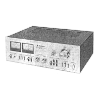
Technics SU-X955

Technics SU-X955
26 pages
To Next Page IconTo Next Page
To Previous Page IconTo Previous Page
Loading...
emoval
of
the
surround/super
bass
P.C.B.,
input
selector
switch
P.C.B.
and
LED
P.C.B.
Ref.No.
|
Removal
of
the
digital
input
P.C.B.
AC
6
outlet
P.C.B.
and
AC
inlet
P.C.B.
+
Removal
of
the
surround/super
bass
P.C.B.
eRemove
the
1
screw
(@).
Procedure
152455
Removal
of
the
input
selector
switch
P.C.B.
1.
Remove
the
3
screws
(@~@Q).
2.
Push
the
5
claws
and
remove
the
input
selector
switch
P.C.B.
Removal
of
the
LED
P.C.B.
e@Remove
the
1
screw
(@).
SurroundAuper
bass
Input
selector
switch
P.C.B.
Procedure
|
Removal
of
the
digital
input
P.C.B.
1-6
1.
Pull
out
the
2
connectors
(J200B,
J801D).
2.
Remove
the
2
screws
(@,
@).
Removal
of
the
AC
inlet
P.C.B.
@Pull
out
the
2
claws
in
the
direction
of
the
arrow.
Removal
of
the
AC
outlet
P.C.B.
eUnsolder
the
2
terminals.
a
-—
4
Cone
Removal
of
the
speaker
terminal
P.C.B.
a
as
|
Checking
of
the
main
P.C.B.
Procedure
|
eRemove
the
3
screws
(Q@~®).
Procedure
|
1.
Remove
the
6
screws
(@~@).
1—6—7
1-6-8
2.
Remove
the
flat
cable
(J207,
J700).
:
P
J207
Oo-—
|
Speaker
baie
}
L
Sos
“9
.
horting
pin
a
®
3.
Remove
the
6
screws
(@~@).
4.
Remove
the
shorting
pin.
6.
Remove
the
3
screws
(B~®).
5.
Pull
out
the
1
connector
(J207).
|
Ref.
No.
Removal
of
the
power
transformer
Ref.
No.
Removal
of
the
power
IC
and
regulator
transistor
10
Procedure
|
1.
Remove
the
4
screws
(@~Q).
168-9
|
2.
Remove
the
fiat
cable
(J700).
|
Procedure
1>8>10
1.
Unsolder
the
power
IC
or
regulator
transistor.
2.
Remove
the
3
screws
(@~®).
Regulator
transistor
When
mounting
the
power
IC
or
regulator
transistor.
Apply
silicone
compond
(SZZOL15)
to
the
rear
side
of
power
IC
or
regulator
transistor.
|
dss
-
Removal
of
the
fan
motor
|
Procedure
1.
Pullout
the
1
connector
(J207).
1-511
2.
Remove
the
3
claws.
Fan
motor
S
a
Rear
cabinet
Fan
motor
Cooling
fan
Projection
.
Insert
a
screwdriver
at
the
root
of
the
cooling
fan.
Force
it
out
of
the
motor
shaft.
.
Remove
the
motor
cover
by
used
©
screwdriver.
.
Remove
the
motor
from
the fan
casing.
.
When
mounting
the
motor
fan,
align
the
fan
casing’s
projection
with
the
hole
of
the
fan
motor.
Fan
case
@
BL

Related product manuals